Welcome to Laser Pointer Forums - discuss green laser pointers, blue laser pointers, and all types of lasers

LPF Donation via Stripe | LPF Donation - Other Methods

Links below open in new window

ArcticMyst Security by Avery

The Inexpensive Engraver Mod Thread

rhd

0
Joined
Dec 7, 2010
Messages
8,475
Points
0
For a long time I've bemoaned the lack of easy user-friendly open source 2D laser cutter / engraver projects. While a purchase from BangGood isn't exactly "open source", at $90, it's hard to complain about this being the base for further development. This thread is meant to be a compilation of mods for the $90 laser "engraver" found here (if other sources emerge in the future, we'll link them up, but so far, this seems to be a BangGood product only):
100-120mW DIY Violet Laser Engraving Machine Kit CNC Laser Printer Sale-Banggood.com (referral code)
100-120mW DIY Violet Laser Engraving Machine Kit CNC Laser Printer Sale-Banggood.com (non-referral code link)

Engraver Modified with 2W+ 445nm 9mm Diode
https://www.youtube.com/watch?v=u2VbAStX6zI


There's an existing thread where this product was initially discussed:
http://laserpointerforums.com/f42/90-laser-engraver-kit-92015.html

If anyone develops a modification for this CNC cutter/engraver, post below, and I'll link you up in the original thread. I'll start us off with the 2.4A driver mod. The next obvious step will likely be some proper heatsinks from the forums machinists.

MODS:

Laser Driver Upgrades:
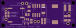
- External Engraver Driver

Platter Upgrades:

Heatsinks:

Other:
 
Last edited:


rhd

0
Joined
Dec 7, 2010
Messages
8,475
Points
0
Here's an external driver BRD and SCH file. This is basically what I'm using now, except that it is one-sided for easier mounting, it integrates a 5V linear regulator for output to a fan, and it integrates some trim-resistors that I needed to use in order to "tame" the output of the engraver's existing circuitry to properly trigger the relay.

attachment.php


The driver can drive at 2.4A. I would recommend a 9V 2A input, but there's some flexibility there. If you wanted to use a 10V supply, that would be fine, and I think it will still run down to maybe 6.5V or so. In my current setup, I'm actually using a 2S lipo battery (7.4V nominal) because I don't have an appropriate wall wart on hand. It's a fairly straightforward driver, nothing too fancy. The engraver's existing output drives a relay that turns the driver on and off. At some stage in the future I may switch the relay to an optocoupler so the everything is solid state, but for now, the relay is working quite well, so the switch is not a high priority.

The RTRIM is there because the existing engraver output is 1.6V when low, and 4.5V when high. I was finding that the 1.6V was sometimes enough to turn on the relay, which obviously you don't want. The 3.6 ohm value for RTRIM is what I found to be a good value. It's in parallel with the relay coil, and it shunts enough current that when the engraver's output is low (1.6V) the relay gets triggered, but when it's high (4.5V) the RTRIM doesn't prevent the coil from triggering. If you find that the relay is triggering when it should be off, then lower the RTRIM value. If you're finding that it doesn't trigger at all, raise this value. However, I would expect that my 3.6 ohm value will work fine for others, so you may not need to deviate from this value.

I have this fan in mind as something that should be relatively easy to mount on a correctly sized heatsink:
http://www.ebay.ca/itm/171468991423...l?_from=R40&_sacat=0&_nkw=171468991423&_rdc=1

The parts list is in the schematic file (double check, and if I've missed anything, let me know, sometimes I forget to list common components if they're parts I have laying around). If you deviated from my RSENSE part to change the current, the formula is 0.25 / RSENSE (ohms) = Current (amps). There are two resistor pads for paralleling resistors if you need to (and the resistors I've selected assume 2x in parallel). Make sure you figure out what wattage the RSENSE resistor(s) will drop if you're departing from the parts I've selected, and pick an appropriate one. Also, I soldered a 100uF SMD cap across the leads of my 445 diode. Not sure if that's neccesary, but I did it to be safe.

Final note. I haven't yet tested this PCB, though it's a driver schematic I've use a ton, and there shouldn't be anything too complex about this, unless I've made a mistake.

File link:
TinyUpload.com - best file hosting solution, with no limits, totaly free
 

Attachments

  • i.png
    i.png
    21.9 KB · Views: 794
Last edited:

ARG

0
Joined
Feb 27, 2011
Messages
6,772
Points
113
I've got a similar laser cutter setup (Arduino based) and I find what really limits these setups are the lack of decent software.
 
Joined
Jan 7, 2007
Messages
6,309
Points
83
Keep going guys -- I got
one coming!
HMike

RHD -- Do you use a fan to keep smoke off the lens?
It looks like you are about 3" above the cut - Right?
 
Last edited:

rhd

0
Joined
Dec 7, 2010
Messages
8,475
Points
0
It probably DOES need a new platter to handle 2W long-term. Even though the existing platter is clear, 2W can create damage to it.

But I must say, with the 2W diode mod, the awesome factor is increased quite a bit.
 
Joined
Jul 4, 2012
Messages
2,834
Points
63
What diode are you using? 2.4A on a 9mm 445 will be more like 3.1-3.2W
 
Joined
Jan 7, 2007
Messages
6,309
Points
83
Perhaps a piece of metal screen or a bed of nails over a beam dump
would make a good backer platter.
HMike
 
Joined
Jul 4, 2012
Messages
2,834
Points
63
2.4A on a laser cutter would result in a pretty short life span.

2.4A would make for a short lifespan regardless of what the diode is in- I thought RHD said he was driving his at that current, maybe I am confusing it with the driver specs.
 

rhd

0
Joined
Dec 7, 2010
Messages
8,475
Points
0
2.4A would make for a short lifespan regardless of what the diode is in- I thought RHD said he was driving his at that current, maybe I am confusing it with the driver specs.

I may have said something conflicting somewhere as I was testing, but what I actually landed on was a 9mm 445 run at 1.8A, which I'm assuming is 2W+.

That said, I'm only using a 3 element lens, not a G9, because I always thought the 3 element lenses made better dots.
 

DTR

0
Joined
Jun 24, 2010
Messages
5,684
Points
113
This is great stuff. Big step up from this one posted a while back using old CD/DVD drive.
http://laserpointerforums.com/f54/mini-cnc-laser-etcher-78491.html

I get tons of people that are doing engraving projects with the 445nm and 405nm diodes. Seems to me that it is getting very popular.

On the lenses I get a lot of people using both three element and single element lenses. It seems with either at the 1-2 inches from the work you can get a very small spot. I would be interested to see if you are seeing any differences in results using the different lenses.
 
Joined
Jan 7, 2007
Messages
6,309
Points
83
How long does it take to arrive?
Also, is all hardware included -
and assembly pictures ?
HMike
 
Joined
Aug 14, 2013
Messages
2,655
Points
63
A black steel sheet, like a piece of an old
computer case, should work well enough as a
beam stop. Muffler/stove/exhaust paint
will reduce reflections. Or just use it
unpainted since you should be wearing
safety glasses anyway, unless it's enclosed.


Top