Welcome to Laser Pointer Forums - discuss green laser pointers, blue laser pointers, and all types of lasers

Buy Site Supporter Role (remove some ads) | LPF Donations

Links below open in new window

FrozenGate by Avery

The I "C" Red Battle Royale LPF Contest

then id like to participate. :D
I was working on this anyway.
8 gram co2, no2 cooled.
spring touch focus.
650nm protective front sight window, for fun goggles still very necessary.
all in a 6061 bare aluminum host with stainless fittings. and sealed wiring.
I have found a battery listed below
I have decided on three parallel 1.8amp drivers for 5.4a
anyway...
the luzy
http://laserpointerforums.com/f50/c-mount-luzy-laser-pistol-85484.html
jn74.jpg

dz17.jpg


finally got the lens, the lens guide tube, and the heat sink rod.
Ordered the drivers tonight.
Also found a perfect battery, Sony camera 7.2v 4800mah NP-FV100 It is just about exact dimensions of the inside of the box. A way better choice than the 2 parallel 9v's with 1000mah.
This contest has defiantly succeeded in its stated goal of getting people like me out of the woodwork.
 
Last edited:


that looks cool good luck!!


then id like to participate. :D

I was working on this anyway.
8 gram co2, no2 cooled.
spring touch focus.
650nm protective front sight window, for fun goggles still very necessary.
all in a 6061 bare aluminum host with stainless fittings. and sealed wiring.
I planned to use a d mag lite with 32650s for a battery box. however funds are rare and limited today and 32650s are not cheap. so I may use other options.
I need all the help I can get with the driver. I have read that some of these X-Drive V6 3A Buck Drivers will do 5a. or I could put 2 2.5s in parallel.
I could also slaughter my 445 for that driver. NO! how can I say that? I am sorry baby. I could never hurt you for another laser.:shhh:
anyway...
 
thanks! :D

here is some evidence of progress.
1d3c.JPG


and a redraft of the plans according to discovery.
3klr.jpg


My thumbs bruised purple bending that stainless trigger guard. labor of love... still not quite straight.

by2h.jpg
 
Last edited:
Judge dREDd==================> JDR-1…. “THE LAWGIVER II”…Form and Function ….
Forged into a Malestrom of RED Photons…..The next step in Hand Held Laser evolution !!!!! A “ Combiner “ !!


The JDR-1 is the CDBEAM entry into the I “C” Red Contest. The JDR-1will contain two (2) five watt 650 C-Mount units from DTR enclosed into a rectangular construct. The Laser Diode’s will both face forward ( one being 90 deg rotated) and the dual beam propagations will run parallel and pass thru two (2) separate 50mmfl Plano Convex optics for collimation.

LD 1 will be the main beam and LD 2 will be the secondary beam. LD 2 beam will then be 90 degree turned via a prism mirror. The prism mirror (Thanx Lasertrac ) will be attached to a Flexmount from LSP for steering. After the 90 degree turn .… the beam from LD 2 will then travel into a PBS cube (Thanx LSP) and join the beam from LD 1. Both beams will then be combined within the PBS cube and their total output will emit from the forward face of the PBS. The PBS cube will be AR coated for the 650 nm line for maximum output.

Planned output is for 8.5W after optics. The next evolutionary step toward a HH-DEW !!!

The JDR-1concept is a radical departure from our standard cylinderical geometry. Function MUST drive form !! Although the basic cylinderical geometry has served us well…We must leave this format behind us for three (3) reasons:

1) The power demands of the JDR-1 are steep. The standard round LiPo cell is no longer the optimal choice.
Instead of individual round cells… in an end-on-end or side-by-side design, the JDR-1 will use a 5000 mAh 11.1
VDC multi-cell pac configurations found in the RC electric hobby area. These pacs all have a rectangular geometry
and the ability to have the individual cells balanced with a Smart Charger. The rectangular LiPo pacs also
enjoy the lower cost supported by the volume sold in the RC hobby.

The RC Lipo battery pacs are charged with micro-processor driven smart charger. Each RC battery pac has a
small multi- wire pigtail which is connected to the charger. This pigtail is in addition to the main power connections.
Through the pigtail link…the processor in the charger is connected to EACH individual cell within the pac. The charger
monitors the charge rate and state of percent of charge for each cell. The processor then “ balances” ALL the cells
within the RC Lipo pac and thereby delivers an optimal state of charge to EACH cell and to the entire pac.
Unbalanced cells have lowered efficiency to hold a maximum charge.

This is ALL existing technology in the RC hobby area. I see NO reason we should not take full advantage of this
technology to propel our designs to the next level !! But…to do so….we MUST leave the Standard Cylinderical HH format….in the DUST !! As our power and other demands grow, a migration to a new form factor for HH units
MUST logically follow.

2) The second reason to migrate to a rectangular Hand Held format is the demands of additional combining optic
components. The rectangular form HH provides a desirable and built-in platform for the combining optics placement. The combining optics are necessary to deliver the next generation of Hand Hand Power Output. This is the evolution of the Hand Held….In my opinion…It is inevitable. The JDR-1 design is based upon this line of logic.

3) As other components of our designs evolve, logic dictates we also incorporate an active thermal management
sub-system. Consider the unit cost of the LAZ-650C and the nature of the C-Mount LD ( Maximum life will be
achieved with lower and stable temps. )… It is the logical next step to utilize off-the shelf heat management
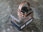
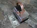
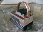
components found in the CPU Over-clocker group. The JDR-1 therefore uses a Dynatron H185 Dual Heat Pipe CPU style active cooler with a 2.45 CFM 70mm x 70mm fan to pull heat away from a solid Copper LD mount / heat sink.
The Copper LD mount is positioned below a solid ½” (12.7mm) Aluminum top plate which also serves as the optical
Platform. Copper was chosen because it pulls heat away from a heat source the most and fastest. Aluminum was
chosen because it is the best metal to dissipate the heat to atmosphere and to the cooler interface plate.


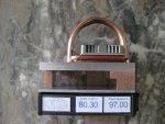
The final support component in the JVR-1 thermal management sub-system is a digital temp meter which will monitor the Copper LD mount core temp. Of course, the actual temp. probe will be located as close as possible to the C-Mount diode.

Along with the evolution to a new rectangular form factor… we must consider the ergonomics imposed by the rectangular geometry !!! We simply need some way to hold and aim the unit. This is accomplished with the pointer cylinderical HH format as a function of the smaller size….the unit simply fits within the typical hand geometry.

NOT so as we increase our overall size and evolve to a rectangular shape….the unit is just too big and too awkward to handle! So…what are our options ?? There are one of two possibilities in this area:

1) A Top-side”D” handle, secured to the top of the unit.
2) A bottom-side pistol-like grip secured to the battery chamber.

I have given this aspect of the design much thought. Although the pistol grip has more ergonomic advantage…I just prefer the top-side handle option…..SOooo…The current design of the JDR-1 incorporates a top-side “D” double Copper tube handle. The handle atop arrangement also contributes to the “ Steam Punk “ look of the JDR-1 / Lawgiver II.

The JDR-1 operating switch is located at the front end of the left fascia of the component compartment. The switch is a three (3) position toggle switch from Mouser (Carling Switch VGD2 0304). The three (3) position switch design has an selection sequence of - Off - On1 - On2.

Off = “All Stop”… On 1 = “Laser Armed”…and On 2 = “Laser ON”.

When the toggle switch is selected to the On 1 position, the red LED will light. The red LED will indicate that the laser is “ Armed ” and ready to “Fire” !!!
BE AWARE of your surroundings and have your Safety Glasses on !!! BE VERY AWARE that you are in control
of an 8.5 watt beam propagation.


When the three (3) position switch is selected to the On 2 position, the Laser diodes will fire and a green LED will light up solid The green LED indicator is right next to red LED. The red LED is mounted in a red Acrylic cube and the green LED is mounted in a green Acrylic cube. Both cubes are located on the back face of the component box.

It is my opinion that such indicator lights are very, very useful for safe operation of the unit. This arrangement lets the operator know….what the laser state is….in a simple and visual manner. Personally…for my piece of mind…I truly enjoy the feature of the unit having an “ Armed “ state…before I can
step up to the “ Laser On “ state !!

The operator’s right hand will engage the Top ”D” handle and the left hand can be positioned to hold the left side of the unit and control the toggle selector switch.

As to the Laser Diode drivers….I will wait for the Lazereer Case + 5A drivers. I feel this is the safest way to go. Considering the investment…I will not overdrive these and I will not run these diodes past a maximum recommended Temp. One driver per diode. The drivers, the LiPo battery, the selector switch, the temp.monitor and the LiPo cell monitor will all reside in the Component box. This box is extruded Aluminum with ABS ends.

Now…on to optics…as with the Tridentis design, combination optics are based upon current Laser Projector art. And ..as with the Tridentis…..all possible use of off-the-shelf components have been incorporated. Why re-invent the wheel ???? The JDR-1 uses a LSP Flexmode mount for the bounce mirror and PBS cube mounting. These mounts secure the optics and provide adjustment to steer the beam and bring both beams into alignment. The compoments fit well within the unit geometry outline….and offers precise and stable beam steering.

The JDR-1 also uses the Thor Labs LA1213-N-BK7 Plano=Convex lens with F=50mm for beam collimation. A single lens is used for EACH beam. The lenses are mounted in the Thor Labs FMP05 Fixed optical mount. This mount has a 8-32 threaded socket on the bottom. The mount is attached to the underside of the ½” Aluminum plate.
In addition…a ½” wide Copper Bar/plate is attached to the upper ½” plate and the lower ¼“ plate. This plate/ connector acts as a stabilizer between the upper and lower plates.

JDR-1 will sport two (2) system monitor sensors:

A Lipo Battery Condition circuit will be used to monitor battery status. The unit will have a digital display located in the side panel of the rectangular component box. The readout will indicate battery percentage charge remaining in the LiPo pac.

A Temp. probe will be located within the C-Mount LD Copper Mount Block. This probe will send signal to a temperature display… which will also be located in the left side panel of the component box.

These sensors supply the basic information needed to monitor power reserve and keep an eye on the C-Mount temp conditions. Keeping with the theme of using existing tech to build upon…the LiPo Battery sensor unit is a standard component in the RC Hobby and the Temp Display is borrowed tech from our friends in the Computer hobby !! IMHO…while operating the C-Mount diodes…these conditions must be monitored to insure safe operations and
protect the serious investment these diodes represent !!! JDV-1 / Lawgiver II does this !!!

Some Philosophical Ponderings…Again…we find ourselves with increased visible coherent power at our disposal….and…with this capability…is an even greater need for safety and responsibility. I cannot stress this fact enough !!!

There is no “ DO OVER” to return lost eyesight….The “ ARROW OF TIME”….It is a ONE WAY door !!! Be safe for yourself and those eyes around you !!

I also propose we label ALL Hand Held units with two (2) or more laser diodes, with the same or different colors combined into a single beam output…with the name of…. ” Combiners ”…as their classification…just a thought ???

See Concept Drawings and the current build pics…not yet complete….but enough so that you can understand the LONG explanation above!!! Enjoy the ride!!! Vote for the JDR-1 / Lawgiver II please !

THANX …AND…CDBEAM=====>

Note: The pics show the build progress so far. No C-Mount diodes, No Collimation lenses, No Bounce Mirror, No PBS Cube.
The Temp Monitor and the LiPo cells and LiPo cell Monitor are ordered.
 

Attachments

  • JD As Built Drawing 8 Series 4.JPG
    JD As Built Drawing 8 Series 4.JPG
    34.8 KB · Views: 244
  • JD As Built Drawing 8  Series 4 with labels.JPG
    JD As Built Drawing 8 Series 4 with labels.JPG
    68.7 KB · Views: 243
  • JdREDd As Built Series 4 Multi View G.JPG
    JdREDd As Built Series 4 Multi View G.JPG
    58.8 KB · Views: 246
  • Ortho View with Monitor Render.JPG
    Ortho View with Monitor Render.JPG
    146.1 KB · Views: 301
  • Side View with Monitor Render.JPG
    Side View with Monitor Render.JPG
    144.1 KB · Views: 268
  • Dollar 4 scale view.JPG
    Dollar 4 scale view.JPG
    157.8 KB · Views: 270
  • Ortho View Back.JPG
    Ortho View Back.JPG
    138.3 KB · Views: 278
  • Three Position Switch.JPG
    Three Position Switch.JPG
    118 KB · Views: 266
Last edited:
Wow :drool::drool::drool::drool:

That looks awesome. I agree, there definitely are advantages with a rectangular housing over a cylindrical one.

Good job REP +1
 
Last edited:
THANX. MATT...As with the Tridentis....this build is also a consuming passion !!!

I have also considered a TEC cooler unit....which could be easily be sandwitched between the 1/2" Aluminium plate and the Dynatron CU radiator.....BUT...ONLY if necessary...for TEC's are very inefficient....and suck much power. We will see !!!

VOTE for the JDR-1 / Lawgiver II Please !!!

CDBEAM=======>
 
Last edited:
Well, since everyone else is revealing their designs, I may as well point out all of the nitty
gritty details of my own. Since the build is not yet finished, I went ahead and did a 3D
rendering in Blender.

(Click for full size image)


The graphics will probably change somewhat. Words replaced, price increased, etc. I'm
already not liking the bar code there. It should be on the bottom and the "ingredients" on
top. The "ingredients" will read, "Aluminum, lithium, silicon, carbon, 5W laser diode,"
etc. you get the idea. :umbrella:

Host:
The body is machined from a solid piece of 6061-T6 aluminum, more specifically Howard
Precision ACC-U-BAR™. When complete it will measure approximately 1.5"H x 1.25"W x
9.5"L. This way there is plenty of mass to absorb the 15-20W of excess heat in the 5W
high mode. Here is a picture of the progress thus far:

attachment.php


The aperture is not pictured as it is out in the garage and I don't particularly feel like going
out there. (It's 35° outside) Everything will of course be polished to a mirror shine. So far
it's all very close to the layout drawings posted previously. (Also in the album linked at the
end of this post.)

Driver:
The driver is an all new design featuring the PIC12F752 MCU. With an onboard DAC,
comparator, PWM, and multiple A/D converters, this single chip does almost everything
short of actually supplying current to the diode. To put it simply, it is a 5 amp buck
converter. Check out this PDF to get a general idea of how this is accomplished.

The startup sequence begins when the switch is turned to the on position. There is a 5
second safety delay during which the LED begins flashing. The laser then comes on in
low power mode.

High power mode is 5 amps to deliver the full 5 watts output this diode is capable of.
Holding the button down fades gradually through 32 dimming modes. Pressing it once
cycles through 5 main modes: 5mW targeting mode, 500mW, 1W, 3W, and 5W. Pressing
twice flashes a code indicating battery level.

I hope that from all of this you can get a sense of what is being accomplished and my
sense of humor. Trying to explain all this does not come easily. There will eventually be a
build thread when things get closer to completion. All of this of course depends very much
on you. I don't have the kind of money some others obviously do and so won't be able to
continue the build without one of the diodes. Hopefully everyone can benefit a little from
the work that is being done.

Photo gallery of the "Big Red" project
 

Attachments

  • 2013-09-23.jpg
    2013-09-23.jpg
    55.3 KB · Views: 744
  • Big Red.thumb.png
    Big Red.thumb.png
    115 KB · Views: 705
Last edited:
There are a lot of awesome entries in this contest. It's difficult to
choose but I think I'm going with CDBeam on this one.


Jerry
 
A big THANX for your vote Laserbee !!! The " Lawgiver II " will be a powerhouse of Red Photons !!!

CDBEAM=======>


Back
Top