Welcome to Laser Pointer Forums - discuss green laser pointers, blue laser pointers, and all types of lasers

LPF Donation via Stripe | LPF Donation - Other Methods

Links below open in new window

ArcticMyst Security by Avery

The Chartreuse Coruscation

Joined
Jul 10, 2015
Messages
9,799
Points
113
Hello….to all you watching the “ CHC Build TV “ !!! Yet another episode !!!

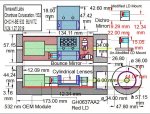
OK…I have been considering this change for some time to the Chartreuse Coruscation … See the attached drawing CHC-H-BE 532 with PP V7.

In the past…I have used a simple rectangular Ally plate to mount all the component on first…to verify the design and alignment geometry. I have then used this plate…to transfer the hole placement as a template to the H-BE frame floor.

The reasoning behind this is….I have ONE shot…to get the mount holes in the right place. IF they end up in the wrong place…..well….ALL the machining work time invested in the H-BE Frame….may go to waste….A new H-BE ,may be demanded. CRAP !!

So…I have been thinking…..how to make this…and future builds….simpler !!

SO….why not….use the Ally template….in a permanent fashion. To do so….will save the need to re-drill all the component mount holes….and the tedious re-alignment process. Just mount all the components to the 3.01 mm thick Component Sub Plate. Do the alignment of all the components ( just once)….and…in a modular fashion….drop in the populated Component Sub Plate….verify centre axis alignment between the Component Sub Plate and H-BE frame….bolt the Sub Plate to the H-BE frame floor…and…we a good to go !!!

If one screws up the Component Sub Plate….just make another !!!!! NO risk to the H-BE unit !!!

Fortunately…the JetLasers 532 OEM…has the perfect base to beam height at 12mm….and a popular USA Ally plate thickness is 3.01mm………so…that is PERFECT….That is what I need to align the JL 532 OEM to the H-BE output elevation.

WHAT LUCK….I just hit a Lottery !!! This NEVER happens….NEVER EVER……!!!

SO….I must machine a slice off the LSP RED LD mount….so that the Red beam is at the exact elevation as the Green beam. THAT is easy to do !!!

I just thought I would share this with you….A EURKA moment indeed !!! SO…you can see…there are always surprises !!!

Unexpected turns and refinements that one can do. Yes….eventually….things….are….what they are !!! So it goes……BUT….there are refinements possible….course corrections….during the build. The CHC build has had a few !!!

Hope you enjoy ALL this detail……for….to some degree…..with such detail….you can be more fully immersed within the build process. You can share in my both good….and not so good moments !!! Hey….hopefully…it is at least….er….ah…..entertaining !!! CDBEAM

View attachment 62567

It's more than entertaining, it's ........enlightening :D


Joined
Feb 25, 2010
Messages
1,643
Points
113
I still wonder how well you will be able to match the beam specs of the 532nm laser with that prism pair. Most of the DPSS lasers have much better divergence specs than even corrected direct diodes. Time and a lot of patience will tell.

While waiting for the 532 OEM Module to arrive from Jetlasers....I have been doing some divergence measurements on the GH0637AA2 Red Diode.
DTR supplied the newer G3 Collimation lens. THANK YOU DTR !! THIS is the best.... on This LD.... As you may remember....I do NOT have the room for a set of C-Lenses`.

SO....I do have room for a set of Anamorphic prism optics. With the first prism set at 140 degree ( Angle of Incidence) to the Red beam axis......I get a divergence of 0.91mRad. That is good !!!
SO...at 36' (11M) a geometry of 12mm width is obtained. The Collimation lens is adjusted to provide a 12mm x 12mm round cornered rectangle.
I predict...This divergence will be adequate to match the divergence of the 532 OEM. Actually....the current Red divergence is less than the posted
1.5 mRad divergence of the 532 OEM module.

SO....I may be able to lower the Angle of Incidence of the first prism....thereby decreasing the power loss associated with Anamorphic Prism optics.
The greater the angle....the greater the slow axis magnification. The greater the slow axis magnification...the lower the Far Field beam divergence will be.

At 0.85A ( Seems to be the knee of this LD )…..power output is about 500W. That is OK....considering the optical loss !!! I would prefer more....BUT.....that is the best this LD will do.

But...as is typical. with optics...the greater the angle...the greater the loss of output power !!! Almost never can you catch a break !!!

Fortunately, Cylindrical Lens optical correction does NOT suffer from this attribute ....but then.....more Far Field aberration is a tendency/possibility with C-Lenses !! Again....the universe seems to always have a " Price to Pay ". This seems to be annoyingly true in the area of optics !! So it goes.

CDBEAM
 
Joined
Jul 10, 2015
Messages
9,799
Points
113
This might have already been said in the previous pages but if not I wonder if you can make your red beam square via. your prism pair then match the beam dia. and divergence of the squared up red with the green by adjusting the output beam expander lens set? As you know what exits the crystal is typically a pretty small dia. and employs a pcx-pcv lens pair that you could tune as well as setting the distance from the crystal and starting dia.
 
Joined
Sep 20, 2013
Messages
17,253
Points
113
The G3 lens has an EFL of 8 mm. Much of your beam improvement is due to clipping of the sides of the divergent line it puts out. This is one way to go, but is it the best? Just something to think about.
 
Joined
Feb 25, 2010
Messages
1,643
Points
113
This might have already been said in the previous pages but if not I wonder if you can make your red beam square via. your prism pair then match the beam dia. and divergence of the squared up red with the green by adjusting the output beam expander lens set? As you know what exits the crystal is typically a pretty small dia. and employs a pcx-pcv lens pair that you could tune as well as setting the distance from the crystal and starting dia.

RC Good point ! Here is the situation;

* The Red LD GH0637AA2 can achieve a mRad of 0.91 @ an output of 400mW - using Anamorphic Prism Pair optics
* The Red New 63283HD Red LD can achieve a mRad of 1.5 @ output of 820mW - using 6X Cylindrical Lens set optics
* The 532 OEM will likely have a divergence of 1.5 mRad ( Not yet verified )

We must solve Four (4) variables at the same time;

* Far field divergence match between the Red/Green LD units.
* Perceived colour of " Electric Lime Green " approx. 555 nm when the dual diode outputs are combined.
* Maximum output.
* Minimum Far field beam geometry.

Hahahaha...that's all !!!

It is a real balancing act !!!....and ...really....I am not sure how it will turn out !!! A more clear path will surface....when I receive the 532 OEM module and experiment !!!!! Enjoy the ride....I know I DO !!

CDBEAM
 
Joined
Feb 25, 2010
Messages
1,643
Points
113
The G3 lens has an EFL of 8 mm. Much of your beam improvement is due to clipping of the sides of the divergent line it puts out. This is one way to go, but is it the best? Just something to think about.

THANX Paul !!!!!!!!! I did not know that !!!!!!!!!! Yes.....since the G3 is a clipper...Yes....that is where I am also losing power !!!

OK....I will NOW go try some different Collimation Lenses...3 element( Another Clipper though ) , G2, F2....and some others....and see what I get for Power Output vs Far field divergence !!!

WOW...always room for and appreciation for learning something new !!! Thanx again !!!

CDBEAM
 
Joined
Sep 20, 2013
Messages
17,253
Points
113
Good luck, Bob. I'm still looking forward to the finished laser. They are always worth the wait.
 
Joined
Feb 25, 2010
Messages
1,643
Points
113
Well....as expected....with a G2 Collimation lens divergence goes up to 2.0mrad...BUT.......Output Power goes up to 750 mW at .9A current in !!
OH....and Prism Pair remains at 140 degree Angle of Incidence. NO FREE LUNCH !!! Will try a Colli with EFL=2 next
The acceptable divergence really depends on what the 532 OEM delivers....right now....THAT is a BIG Wild Card !!!

Note: I may end up with the Red New 63283HD LD with a set of Cylindrical Lenses....BUT....to do that....I MUST modify the H-BE frame....and make the saddle length longer. Things seem NEVER to be easy !!

CDBEAM
 
Last edited:
Joined
Sep 20, 2013
Messages
17,253
Points
113
You're right. There's no free lunch. The G2 has an EFL=2.39 mm, so don't expect much difference at 2 mm. Sometimes you just have to rethink your project to get where you were hoping to all along.
 
Joined
Feb 25, 2010
Messages
1,643
Points
113
Yes....a " Rethink " was done !! Well....I have decided that the Anamorphic Prism Pair SUCK too much Optical output !!! I will go back to the original plan....a set of 6X Cylindrical lenses ( From the recent Group Buy ) !! See drawing attached CHC-H-BE with 532 Mod Blivitz 7

So...the Best Output Power, Lowest Beam Divergence yet achieved with several LD's trialed;

GH0673AA2 LD
2MM /EFL Collimation Lens
Output achieved = 663mW
Current in @ 0.90A
Near Field beam @ 3mm dia.
Far Field beam @ 13.95mm wide x 13.50mm height ( @ 36' / 11.0M )
Divergence achieved @ 0.997 mRad
6X Cylindrical corrective optics

Not Bad !!… All other LD's ( HL63193 and 63283HD ) tested delivered minimum 1.55 mRad !

SO....this is how I will go !!! I can only hope this is enough Red Photons.... when combined with the 532nm line....will deliver the " Electric Lime Light " colour I seek !!

Jetlasers have shipped the 523 OEM. I will likely need to mount the 532 OEM driver board external to the host case...….just the way it goes !!
I am toying with the possibility of fabricating a nice Brass handle....like a drawer pull....and mounting the driver inside the handle ???....and attaching the handle to the OD of the Host unit......This add-on will be Less streamlined....more Steampunk....So it goes !! Not sure how this will look ???? The Build is already honk 'in long with the Beam Expander on the front !!

Note; a return to using the Cylindrical Lens optics will demand opening up the flat platform length on the H-BE frame to 124.40 mm......just NO other way !!

CDBEAM

CHC-H-BE with 532  mod BLIVITZ  V7 .JPG
 
Last edited:
Joined
Feb 25, 2010
Messages
1,643
Points
113
Well....After much " Moving the furniture around "....IT LIVES.... I now have a working combiner unit....to bolt into the H-BE unit.
I really like the modularity of this design.....See the attached pics. I am at the stage now where this unit is ready to be put into the H-BE unit.

I can say....What a complete PITA this was !!!. That is because....I had to cram everything onto a somewhat small Sub Plate ( MSP ) See attached drawing CHC H-BE Only V9 drawing. JUST ENOUGH ROOM...1MM TO SPARE !!! WOW !!!

As you can see....the foot plate from the LSP Brass LD mount was eliminated. The Brass Mount itself was shortened to match the beam elevation of the JetLasers 532 OEM.

I had an other technical difficulties !!! Beam parallel propagation off-axis pitch was an issue. Solved the condition...…..but then....I Demand as close to perfect as possible. Beams MUST be parallel to the mount when adding the demands of the Beam Expander optic. Pitch, Yaw, Elevation and beam centering are critical as the beam or beams entre the Beam Expander unit. There is just no room for error.

Anyway......See the pics. In one pic....you will note a temporary mask I used to cut some stray vertical wing presents. This masking will automatically take place when the entire unit is bolted into the H-BE component....as the combined beams must pass thru the bore hole located in the front of the H-BE.

As for Beam divergence geometry matching....I am very, very pleased......whereas both beams seem to have very, very similar divergence.... I would say this is a result of careful planning.....mmmmm.....NNAAAHHH....just Good Luck !!!.....

Then....the GH067AA2 surly needed C-Lens correction......That is what brought this beam to an acceptable divergence !!!

I see NO overlay, spillage of Red over Green....Or....Green over Red !!! at 15M.....now....maybe at a Click distance.....we may have some spillage......Dunno…..But then.....as with ALL beam Combiners.....we can only get close....NEVER PERFECT !!!!!

As for Colour blending....Perfect....to my eye !!! I can go from the Grass Green of the 532.....to Lime Green....to a nice shade of mainstream Yellow.
THIS is what I was after !!!!!!!!! …….. In something with some power !!!

Hope you enjoy the ride !!! Will continue to post my journey as we go into the home stretch !!

CDBEAMCHC H-BE BLIVITZ  V9.JPG20190202_115355_001.jpg20190202_115442.jpg20190203_205450.jpg20190203_210654.jpg
 

Attachments

  • CHC-H-BE with 532  mod BLIVITZ  V24.JPG
    CHC-H-BE with 532 mod BLIVITZ V24.JPG
    255.2 KB · Views: 21
Joined
Jul 10, 2015
Messages
9,799
Points
113
Congratulations, it was a long battle but now your victory has now come to light.
Shine baby shine, bask in the limelight. (y)
 
Joined
Feb 25, 2010
Messages
1,643
Points
113
THANX RC !!! This build has had MANY twists and turns !! The most surprising....the inability to mix the 520nm line with the 637nm line to produce a decent lime green...That was unexpected !!! I am not clear as to why that was !!! But I assure you....it was so !!
That demand for the 532nm line....really threw this build into chaos !!

The take away here....design and build the MSP.... populated with LD's and combining optics to provide POC....THEN....Machine the H-BE. I was very lucky to have just enough room....and now....I must re-machine the flat on the H-BE component. I will do this re-machine....er…." live"....meaning....I will have the ability to place/check the beam elevation with the BE in place and 532 OEM fired up !!

SO....I can always shave off some additional Ally to lower the beam elevation. As noted B4....the beam's MUST enter the BE....with complete precision...
Pitch, Yaw, Up/Down, and Left/Right centering MUST be spot on.

Anyway....pass the popcorn !!! Next build....Hmmmmmm....Likely the Blue Katar !

CDBEAM
 
Joined
Sep 20, 2013
Messages
17,253
Points
113
Nice job, Bob. That was certainly filled with unintended consequences. Thanks for sharing the experience here.
 
Joined
Feb 25, 2010
Messages
1,643
Points
113
Thanx Paul !!!! NO ONE else provides such build detail....Perhaps....it is of little or no interest ???? Dunno ??? I will continue my Solitary March....Ad Nauseum !!!!

At some time in the future...others may follow....or...technology will eventually deliver a Direct Injection LD...@ 555nm.....with 1W or greater !!! with less than 2.0 mRad divergence !!!!!
OH....AND......that does not cost the price of a good used car !!!! HAHAHAHA !!

I predict....Such a 555nm Diode will be not be here soon !!! There is NO commercial application driving the need for the 555nm line....that I know of........SO....we will not be enjoying that fallout tech for a long time !!! Sigh....HMMM....maybe they will get the crystal stability issue solved....but....I want One (1) Watt....not a LAMO 36mw !!! ...AND at 555nm....NOT 565nm !!! Do not hold your breath for this option also !!!

Until then....THIS is the way to go !!!

I must mention the JetLasers 532 OEM was of very good build quality. I would beef up the +/- wire seal coming into the unit ! Divergence was just under 2.0 Rad. Beam geometry was circular and well defined. Power output was 530 mW. This was THE smallest unit I could find !!!....It is quite small !!! The price was very, very reasonable...around $ 200 USD. I am very happy with this component !!!

Now....the HL0673AA2 LD was....flawed !!! The Beam axis was NOT perpendicular to the diode case. I tried several LD mounts....no effect. Now...because we are going thru a set of cylindrical lenses....we only have two (2) radial positions to choose from !!! ….( Remember....we MUST present the fast axis beam divergence....perpendicular to the C-Lens flat lens bottom )

In the " A" orientation....the beam was pitched up !!!....SO...NOT parallel to the MSP plane !!.....and in the "B" orientation.....the beam was pitched down !!!....again NOT parallel to the MSP plane !!. I opted for a 0.11mm SS shim stock placed at the rear of the LSP Brass LD mount.....between the mount and the MSP !! ( With the LD in the " A" position ) …. THIS delivered a parallel condition.

I must note.....the Main beam 532nm (Green)…..was the geometry/beam path to train to !! It was critical....that the 637nm (Red) beam be completely centered inline with the 532nm beam....at the Dichroic plane surface. This is the condition wherein the beams can be on a coaxial path !!! If this condition is NOT meet....one will NOT achieve a combined beam propagation. Optics are a demanding Bitch !!!

SO.....please benefit from my learning curve !!! These Combiner units....coupled to a Beam Expander.....are very, very challenging !!! We can do it....not easy, not quick....but it can be done !! THIS build has been a " Work in Progress " since May 2018...9 Months !!!!

Hope you are enjoying the ride !!

Note: The " Igor" pic is included as a tribute to the HL0637AA2 Diode internal alignment !!!

CDBEAM
 

Attachments

  • big_thumb_marty_feldman_young_frankenstein_desktop_1024x768_wallpaper-41883.jpg
    big_thumb_marty_feldman_young_frankenstein_desktop_1024x768_wallpaper-41883.jpg
    10.9 KB · Views: 1
Last edited:
Joined
Dec 9, 2011
Messages
221
Points
28
Strange about the offset red diode. With the HL0637AA2, you are getting about 1mRad with a 3mm aperture? Thats pretty good. How is the far field spot? any pics of just the red FF?


Top