Welcome to Laser Pointer Forums - discuss green laser pointers, blue laser pointers, and all types of lasers

Buy Site Supporter Role (remove some ads) | LPF Donations

Links below open in new window

FrozenGate by Avery

The Chartreuse Coruscation

Thanx LS....I will go down the most simple, smallest , non-invasive path. I want the digital meter to ride with/on the Host OD.

SO....one can measure across the Driver Modulation 10K pot....yes....for it regulates 0-5 VDC going into the BB8A driver. Thanx for that idea !!! I really do NOT need to know what mA are being fed into the LD. All I need is a digital read out.....which correlates to LD Optical Output !!!!! I can use the digital readout to " Bookmark " the position of the 10K pot....and thereby...." Bookmark " the Green:Red ratio......associated with THATposition of the 10K modulation pot !!! I will try this option first.

VDC Digital meters are very small....smaller the Hall Effect Ammeter....so...that is good.....and this method would eliminate the space needed to mount the Hall Sensor !

I have some very small VDC digital units !!!.....I will tinker !!!

I MAY actually have room to mount the small VDC meter...INSIDE the host cavity....DUNNO !!!! To mount the VDC meter internal...Cutting a rectangular/square hole....thru the host wall....will be challenging !!!

Hmmmm...Nothing good...is easy !!!! Thanx again !

CDBEAM


I've got fairly far-off plans to develop a digital driver /w enough smarts to measure all relevant voltages and currents needed (well, it wouldn't measure the output current as the processor would set it instead, but it could still measure input current/voltage...) and report them on a little OLED display but the current measurement techniques up here seem like they'd work pretty well.

That future driver isn't going to be small to start with but i'll try and prototype something going into the new year...
 
Hi Paul,

Sorry, I do not find the quote button in this new LPF version.

"So, you didn't measure the current through the laser diodes, but measured the current pulled from the batteries? I have seen this done, but it defeats the need to know the exact current the diode is pulling. I don't understand why trying to measure at the diodes caused you a short circuit condition, though. "

No, I mesureed the current through the laser diodes in the output circuit of the driver. The problem was that the feed wires of the ammeter should not be attached to the same contacts (output of the driver) but to the input contacts of the driver.
By feed wires I mean small wires to keep the display shine.

Here is my old thread where all about that build was reported with pictures:
https://laserpointerforums.com/threads/making-a-6-6w-blaster-465nm.97587/
 
Sorry if I read your post wrong. I will check out your ammeter in series with the LD that you linked to. I must have missed it the first time around, or forgot it, as I don't remember anyone successfully measuring diode current in a build before.
 
Well....I have reviewed my space available inside the host Switch/pot section. I DO have enough room to slip the Hall Effect sensor....inside the host tube....Hmmmm...Might just try this....as this Hall Effect meter.....May ALSO be able to set the current on a given driver.....Maybe ???....SO......
Hey….for $ 12.….I will likely tinker around with this concept !! Why not ??

CDBEAM
 
Something tells me the hall type sensor is not gonna be very accurate/ repeatable. Interested to see how it works. I could think of a lot of things to use them on myself. Also, I wouldn't make too many loops around sensor to boost resolution because it will create an inductor. Not something you want in series with the LD. Maybe not a problem but potential is there. Especial with a switching type driver.
 
The Hall effect occurs with conductors, or better yet semiconductors, where you have a voltage applied at a right angle to a magnetic field which is also at a right angle to a current flow. I have seen them used in the past as position sensors in servo circuits, but I can see how they might also work for a current sensor if the applied voltage and magnetic field are held constant. You could get a Hall effect with a piece of copper, but the sensitivity would be lower when compared to a semiconductor. The main advantage would be a low resistance to the flow of current, so it would have little voltage drop in the current sensing portion of the Hall device.
 
Well....OK...to avoid a secondary induction coil...I will limit the # of wire-loops thru the coil to 10. That should still deliver a resolution of 30 mA....I think. If this method fails to provide a " repeatable result "....I will defer to reading the 0-5 VDC off the external modulation pot.

I continue to be in contact with Jetlasers regarding the 532 OEM module. They are really supportive !!! I will do a review of this 532 OEM module when I receive it.

I am waiting on delivery of the GH0637AA2G Red diode from DTR. I need to verify that the collimated output is about 2.0 mRad.

Thanx again for your input !!

CDBEAM
 
You can get ~2mRad with a 10mm EFL lens. The FA divergence is 0 or less with a 10mm lens. at least in the first 150 feet or so. Very "bar shaped"
 
You can get ~2mRad with a 10mm EFL lens. The FA divergence is 0 or less with a 10mm lens. at least in the first 150 feet or so. Very "bar shaped"

Hmmmm ??? I may be forced to have the Prism Pair in the RED beam path....or....maybe de-focus the Collimation lens a bit ?? so as to match the FF geometry of the Green beam. The goal is to achieve a beam-on-beam condition. I will see soon.... Thanx !

CDBEAM
 
Last edited:
Log squared is the right way. Put a one ohm resistor in series with the diode and measure the voltage across it
But....this will only work for a static beam. If you modulate the diode what you measure will be wrong. It’s a lot more complicated to measure ac modulation accurately and then you have to chose what it means to you. Rms, average.....those two are the most common. Your volt meter is set for 60hz or 50 hz. Your m9dulation is likely different and changing. When we talk about setting the current on a diode it usually means the dc current.
 
Still experimenting with the GH0637AA2G Red diode. Looks Good !!! I WILL need the Anamorphic Prism Pair to dial in the Red LD divergence !! Well...time to take the plunge and order the Jet Lasers 532 OEM 500mW Module !!

I received the Ammeter unit. The sensor component is larger than I expected !! Well....I will likely go with the method of measuring the 0-5VDC across the 8A driver modulation pot !!! All I really want is the ability to reset the modulation....to the same 0 - 5 VDC value....and thereby repeat the amount of Red Photons into the Green/Red mix....so....just a goal of repeatability. I DO have room for the small digital VDC meter !!!

Hmmm...I suppose I could use a 10K Rotary Encoder.to provide a digital readout....which in turn would deliver repeatable Green/Red mix...never experimented with these !!! Thoughts ???

The Saga continues !! Enjoy the ride !!

CDBEAM

Added note....Oh Shit...Quadrature Wave form, Relative/Absolute, Signal bounce....The World of Rotary Encoders !!! To those with a rudimentary command of Electronics…. Oh, Oh ...Ho, Ho. Ho !!! I just took a quick trip down the rabbit hole !! I will continue to TRY to educate myself....alas...".I am a Stranger....in a Strange Land " !!! I know...there are many of you...who laugh at my Neanderthal Level grasp on Electronics...I laugh with you !! So it Goes !!!

I really do not want to wade in that deep....coupling an Adriano containing unit....to obtain the shaft rotary position readout....What a can'o'worms !!! ….Maybe I will just stick with a simple /small digital VDC....reading the VDC delivered to the control modulation input....we are not going to the Moon here !!!
 

Attachments

  • bf1.jpg
    bf1.jpg
    25.1 KB · Views: 5
Last edited:
Put a pot between the modulation inputs of the red and green. Adjust the mix between the lasers with a single modulation input on the wiper of the pot. This will set a color mix between the lasers. Now try varying the modulation from off to full on. Likely the mix will change but if the variation is acceptable your done. If not, then you have a complex control problem. Otherwise you’ll need a table of some kind that stores the curves that make the color you want from 0-5v. Try the single pot and try to be happy with it.
 
JetLasers 532 OEM 500mW module on the way. As stated....I will use the Prism Pair...to attempt to match the divergence of the Red Sharp 0637AA2G LD....to the 532 Module beam !!

As to the measurement of the Red Beam output....I am fairly sure I will go with a simple measurement of the 0-5 VDC modulation signal. This will deliver repeatability of the amount of Red photon's into the Green/Red mix.....thus following the KISS principle......something I rarely DO !!!

SO...the Green 532 module is the main beam....and the Red 0637AA2G LD is both optically corrected and driver output modulated...with both the correction and modulation inserted so as to match the beam geometry of the Green 532 module and achieve the " Electric Lime Light " perceived color mix I am after.

Maybe someday...they will just make....er….a 25W diode with 1.0 mRad divergence @ 555nm....Sigh !!!

See latest render...FYE !

CDBEAM
CHC-H-BE with 532 -PP V4.JPG
 
Last edited:
I still wonder how well you will be able to match the beam specs of the 532nm laser with that prism pair. Most of the DPSS lasers have much better divergence specs than even corrected direct diodes. Time and a lot of patience will tell.
 
Hello….to all you watching the “ CHC Build TV “ !!! Yet another episode !!!

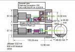
OK…I have been considering this change for some time to the Chartreuse Coruscation … See the attached drawing CHC-H-BE 532 with PP V7.

In the past…I have used a simple rectangular Ally plate to mount all the component on first…to verify the design and alignment geometry. I have then used this plate…to transfer the hole placement as a template to the H-BE frame floor.

The reasoning behind this is….I have ONE shot…to get the mount holes in the right place. IF they end up in the wrong place…..well….ALL the machining work time invested in the H-BE Frame….may go to waste….A new H-BE ,may be demanded. CRAP !!

So…I have been thinking…..how to make this…and future builds….simpler !!

SO….why not….use the Ally template….in a permanent fashion. To do so….will save the need to re-drill all the component mount holes….and the tedious re-alignment process. Just mount all the components to the 3.01 mm thick Component Sub Plate. Do the alignment of all the components ( just once)….and…in a modular fashion….drop in the populated Component Sub Plate….verify centre axis alignment between the Component Sub Plate and H-BE frame….bolt the Sub Plate to the H-BE frame floor…and…we a good to go !!!

If one screws up the Component Sub Plate….just make another !!!!! NO risk to the H-BE unit !!!

Fortunately…the JetLasers 532 OEM…has the perfect base to beam height at 12mm….and a popular USA Ally plate thickness is 3.01mm………so…that is PERFECT….That is what I need to align the JL 532 OEM to the H-BE output elevation.

WHAT LUCK….I just hit a Lottery !!! This NEVER happens….NEVER EVER……!!!

SO….I must machine a slice off the LSP RED LD mount….so that the Red beam is at the exact elevation as the Green beam. THAT is easy to do !!!

I just thought I would share this with you….A EURKA moment indeed !!! SO…you can see…there are always surprises !!!

Unexpected turns and refinements that one can do. Yes….eventually….things….are….what they are !!! So it goes……BUT….there are refinements possible….course corrections….during the build. The CHC build has had a few !!!

Hope you enjoy ALL this detail……for….to some degree…..with such detail….you can be more fully immersed within the build process. You can share in my both good….and not so good moments !!! Hey….hopefully…it is at least….er….ah…..entertaining !!! CDBEAM

CHC-H-BE with 532 -PP V7.JPG
 
Last edited:


Back
Top