Welcome to Laser Pointer Forums - discuss green laser pointers, blue laser pointers, and all types of lasers

Buy Site Supporter Role (remove some ads) | LPF Donations

Links below open in new window

FrozenGate by Avery

The Chartreuse Coruscation

That's very interesting that the red diode's beam was not perpendicular to the backing plate, I have suspected as much could be at play and I bet that's also happening with the blues sometimes and it's part of the problem, it all means adjustable mounts or hand fitting but also means it's not always the module seat that's solely to blame. Good info Thanks. :)


Sorry LS....Out of town last week.....OK....Will get a pic of the FF spot. Looks really well matched to the DPSS. Some wispy Vertical Wings....I predict the BE will remove the majority of them.....along with the masking of the H-BE output !

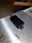
Working on a method to incorporate the 532 OEM driver unit into a Handle/Standoff. This driver box...is not small !! The driver box is 89.45mm long x 46.45mm wide x 29.0mm tall.

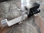
SOoooo....I decided to incorporate this unit as a Handle/Standoff. See the attached pic. I removed the stock ends from the driver....and have fabricated two (2) end plates from 12.5mm thick Acrylic sheet to act as end plates. This arrangement will then become a handle of sorts !!!

The Acrylic plates now have been machined to form a semi-circle socket on one end....and the driver will be sandwiched....between the front Acrylic plate and the rear Acrylic plate. Power in/Power out and I/O light and switch will both be relocated to be located in the Acrylic plates.

Now....this is the only location that this " Handle" can be placed...unfortunately...it is NOT a balance point. This build is front heavy ...and this handle...is located too far to the rear.

When placed upside down on this handle......the unit will tip down ….. Oh Well. That is the way it goes. !.....I will need to fabricate a dedicated/custome stand....for display/storage !! This build just keeps getting bigger and bigger !!

See the removed - (black) stock end plates in the pic. See the original driver pic also attached.

I still must re-machine the H-BE to accept the larger optics train.

Getting near the end !!!!! TOOooooo Bad !!

CDBEAM

Note: Yes RC...I bet we have had this issue happening on some LD's B4....where the Axis propagation.....is NOT perpendicular to the LD case back.....WTF ????? I tried many ways....but am positive the beam was crocked !!! I can compensate....but at considerable time/energy !! CDB


63431
 

Attachments

  • 20190210_115813.jpg
    20190210_115813.jpg
    70.7 KB · Views: 17
Last edited:
Yea....Lotsa beam shots will be headed this way !! Gotta do the Red FF for LS....tomorrow....

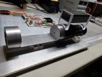
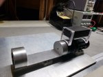
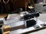
See the attached pic..... Works in Progress ...with the handle in position...not yet fixed....and nothing else in place yet….I just had to see how it would look....mmmm….I think it looks OK ???? Not Bad....NOT that I had a choice....as this is the driver that Jetlasers supplied. IT'S GOTTA GO somewhere !!!

IMNSHO...this is the best placement I can deliver ! Not the standard Hand Held....BUT THEN....Not Much standard about this build !!

Later....CDBEAM63435
 
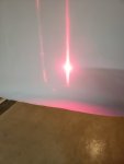
LS....See FF of Red only. Top/Bottom wing much more pronounced in the pic....not real life. BE should reduce these down considerable. FF @ 3M distance from output. Divergence @ 1.0 mRad. Spot geometry @ 7.5mm

See pic of Jetlasers 532 nm OEM driver enclosure adapted as a handle for the build ( Black box with Acrylic Endcap plates attached front and rear )...just another " Curve in the Road " driven around !!

CDBEAM


6345763458
 
Could you replace that large driver with a BB8 or the 5500 as it's just driving an 808nm pump diode Right ? or is there a TEC also ?
 
RC....I specifically requested no TEC to Jetlasers. No real need in this application. Hmmmmm ???? Gotta think on this one. I surly have room for one more BB8 unit....encased inside the host front. I thought about this option....but just did NOT want to fry the 808 pump Diode.....If this were to occur....well, the whole Module would be junk !!

Hmmmm ????? I will consider this....but now....I do have a functional and aesthetically pleasing handle !!! What to do....What to do !!!

In addition....I now plan to attach a ultra small / digital VDC meter....to the surface of the rear Acrylic plate. This meter will measure the VDC supplied to the BB8 driver control input....that I am using to power the AA2 Red diode.

This meter will display 0-5 VDC.....and it is this voltage signal which determines the current input to the AA2.

I asked JetLasers if they had a smaller driver ?? Nope !! They did not !! They (Jetlasers ) sure have the smallest module....and the best price !!!!

I will reconsider this option....but am leaning at keeping what I have....Larger build / Steampunk look and all!!!

Thanx,
CDBEAM
 
Last edited:
Well.....I will likely keep the " Driver Camouflaged as Handle " design....I like the looks....and....honestly....I want to finish this build !! I have so many other projects to work on.....and well....it looks good...IMNSHO...kinda balances out the profile......Hmmmm ??

It is not like this Handle addition will limit the portability of this build. The build attribute of being a normal size pointer...was gone from the very start !!!
A small to medium size, build....is NOT optional with this level of complexity, power and optical properties !!! Not with what diodes we currently have to work with !!!....SOooooo...Steampunk it is !! Really, all things considered....with what we are doing here....I cannot imagine a more compact package.

CDBEAM
63483
 
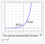
Hmmmm...My builds follow the graph below....somewhat exponential....always L O N G....but then....they supply some degree of extended...er….ah...entertainment !! We are to the point now....when all is coming together !! Quickly...Some steps remain !!

The H-BE still requires modification....as in lengthening the flat saddle seat....and lowering the depth slightly. This is a critical step....as the elevation Must be spot on....as to deliver a centered beam to the Beam Expander optics.

We currently stand at 186 posts to this thread !!! WOW...but...not really surprising….considering ALL the twists and turns in the build path !
If there is a better way to combine higher power LD's....and correct the beam....I would luv to see details. ….That said...Sanwu….please provide detailed drawings to your RGB unit !!! HAHAHAHA !! Ya right !!! The Sanwu is a combined RGB of 480mW ( As advertised )....all single mode diodes....with only R/G.....there would be 280mW output.....vs the CHC @ approx. 1200mW !!

I wonder what yellow/green combined colour this unit produces....as I would assume....the Green is an direct LD....so...output @ 520nm....something I found....unacceptable to mix with the 637nm Red !! Whatever. So it goes !

Later,
CDBEAM


63484
 
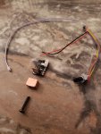
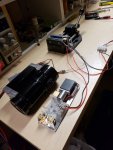
Well....Been three (3) months !!! Got the Wossee L5000GT driver....and the Special order PWM control !!! ( Also from Wossee } Back around April 1....See pic.
Been busy with Eurorack modules !!!

See the pic for custom machined CU Standoff post....to mount the driver inside the Host Body.....Time to FINISH this !!! I am back into Laser Shows again !!!! I must have some form of ADD....for I keep jumping from ….project to project !!! Just the way it is !!!

CDBEAM
 

Attachments

  • L5000GT Driver and mount_ Wossee PWM unit.jpg
    L5000GT Driver and mount_ Wossee PWM unit.jpg
    79.7 KB · Views: 11
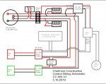
Well....the build goes on. For the detail interested ( If Any )….see the wiring schematic attached !!
YES.....this build WILL look rather " Steam Punk " when completed !!! THAT became obvious when the external
532 Driver box was adapted into a handle...of sorts !!

Meters to monitor the LiPo cell voltage....one (1) meter for each two (2) Lipo 18650 cells will be mounted onto the side of the 532 Driver enclosure. A RMS display meter will be mounted atop the 532 Driver enclosure. This meter will be used to read the Pulse/second output of the PWM unit.

A PWM unit( Custome built by Wossee )….. will put out a pulse....which is feed to the L5000GT Driver. The speed of the pulse sets the current output of the driver for the Red Diode. Also....the PWM unit requires 5 VDC.....SOoooo...I had to add a DC-DC converter ( To be mounted on the other side surface of the 532 Driver enclosure)....to go from the 8.4 VDC down to 5 VDC.

A secondary Laser On I/O switch will be located just forward of the DC-DC converter. SO....the Main I/O switch turns all the system display units on....and the final Laser discharge will have it's own dedicated switch. Lot'sa things will be hang'in off the Green Driver enclosure !!! That is just the way the build has evolved !!!

Think about it....Centuries in the future.....there will be modifications to DEW's.....all kind'sa modifications.....New Antimatter Power cell's......On-Board Gyroscopic Stabilization...Liquid Helium cooling Serpentine….Maybe new temperature monitoring for the Power Core and Photon Converter....????? Whatever ???? Just as we modify and modify things today...high value items will be modified then !!! ....,An "Overheated"...."Underpowered"..... Ray Gun is....well.....useless !!!

This CC build may not look Streamlined !!!!...but...it is functional.....And it will kick ass in the Yellow/Green colour !!!!.........And I say to you " Duck Rogers in the 25th Century " RAZZBERRIES " !!!.....I aim " Reverse Spin " Photons....in your General Direction !!!

Note: Started THIS build....exactly one (1) year ago...Like a good whisky.....gotta age this shit !!

Note: added further explanations 5.19.2019

CDBEAM
 

Attachments

  • CC  Schematic 7.JPG
    CC Schematic 7.JPG
    89.8 KB · Views: 10
Last edited:
Finally !!!!! some progress.... Been brining my NOS Logan 820 Lathe up to speed for the last 6 Weeks !

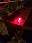
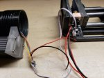
SO.....See the attached pic. PWM unit from Wossee works PERFECT....One can dial in the amount of Red Photons needed to deliver a perfect Chartreuse color !

The PWM unit has the Pot/adjustment wires ( Last pic on the left) going into the host barrel section and then, via the white cable, feeds the L5000TG Wossee driver with a pulse. I will use a dedicated meter ( not shown) to read the pulse count, and this read-out will be used to guide the setting for color repeatability. IF I ever did a RGB unit, I would want such a feature for ALL three colors.

Also, MAY be incorporating a new experimental micro latching circuit ( provided by Brian ) as the final I/O switch for LD.s. More details later. THANX Brian !

This build moves as quick as ALL my builds....The speed of the Lambert Glacier !!
As the Great Wheel rotates in a clock, as the Verge oscillates and meters out the seconds....so do my builds move...
" Inch by inch….Step by step....Niagara Falls " HAHAHAHA

Later,
CDBEAM
 

Attachments

  • CC Red Modulated set-up.jpg
    CC Red Modulated set-up.jpg
    88.2 KB · Views: 13
  • CC Red Modulated Powered up.jpg
    CC Red Modulated Powered up.jpg
    60.4 KB · Views: 14
  • L5000GT unit with CU Heat snk.jpg
    L5000GT unit with CU Heat snk.jpg
    136.3 KB · Views: 15
Last edited:
The speed of the Lambert Glacier

Then with global warming you should be getting faster.
Also are you referring to the melt front retreat or the sub glacier melt rate of the actual advance rate. You are so non specific (rolls eyes)
 
Melt Front Retreat....of course !!! :devilish::devilish:
I just get SOOOooooo distracted.....SOOoooo easily...it is a wonder....ANY project of mine is completed....But then....I think I enjoy the build SOOoooo much.....a passive / aggressive behavior modality slows down the progress I suspect !!

Oh....and to Mr K....." He tasks me, he tasks me " hahahaha

Later,
CDBEAM
 
Last edited:


Back
Top