
Welcome to Laser Pointer Forums - discuss green laser pointers, blue laser pointers, and all types of lasers
How to Register on LPF | LPF Donations

Navigation
Install the app
How to install the app on iOS
Follow along with the video below to see how to install our site as a web app on your home screen.
Note: This feature may not be available in some browsers.
More options
You are using an out of date browser. It may not display this or other websites correctly.
You should upgrade or use an alternative browser.
You should upgrade or use an alternative browser.
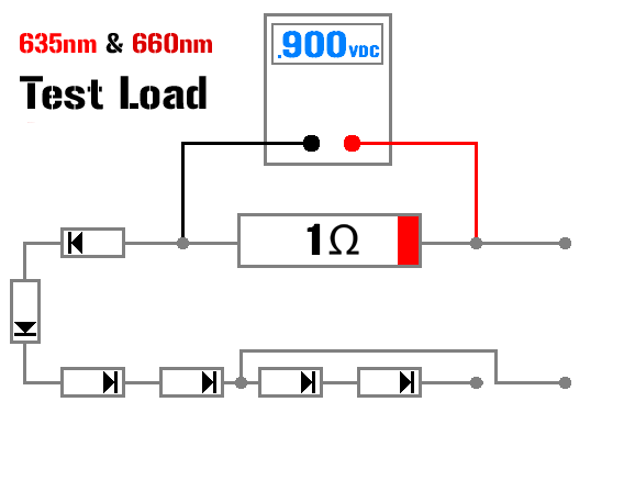
Test load for red
- Thread starter ped
- Start date


- Joined
- May 4, 2009
- Messages
- 5,426
- Points
- 113
Some people are using these 

and you can get one here> http://laserpointerforums.com/f64/fp-super-3-amp-test-load-62826-4.html#post894284

and you can get one here> http://laserpointerforums.com/f64/fp-super-3-amp-test-load-62826-4.html#post894284
LaZeRz
0
- Joined
- Feb 19, 2011
- Messages
- 2,549
- Points
- 63
i think hes asking for voltage :thinking:
EDIT: maybe not, but those testloads from FP are awesome
EDIT: maybe not, but those testloads from FP are awesome
Last edited:
- Joined
- May 4, 2009
- Messages
- 5,426
- Points
- 113
Well first he asked what we were using then he asked for diagrams.
So I showed him something he could use :na:
Now why don't you show him a diagram...
So I showed him something he could use :na:
Now why don't you show him a diagram...
Blord
0
- Joined
- Dec 24, 2007
- Messages
- 5,356
- Points
- 0
I use a selfmade testload, poor-man version.
There are 2x2Ω resistor in parallel to even out the load.

http://www.rog8811.com/laserdriver.htm

There are 2x2Ω resistor in parallel to even out the load.
http://www.rog8811.com/laserdriver.htm
Last edited:

Blord
0
- Joined
- Dec 24, 2007
- Messages
- 5,356
- Points
- 0
Condolences with the loss of the Mitsubitsi 638nm diode. I use my testload with the diode without problem. Few seconds below 1A should be okay as the testload heat up very fast at high current.
")

Fiddy
0
- Joined
- May 22, 2011
- Messages
- 2,736
- Points
- 63
rhd
0
- Joined
- Dec 7, 2010
- Messages
- 8,469
- Points
- 0
I just want to point out that the normal RED logic fails us with respect to test loads for the 635s.
At 1A, those 1N400X or 1N540X diodes start to drop closer to 1V each. If you're placing 4 of them in series, and also dropping ~1V across the resistor, than you're really talking about something between 4.5 and 5V of simulated Vf.
IIRC, these Mitsubishi reds only have a Vf of something like 3.5, when run at 1A (that's a rough memory though - confirm before taking my word for it)
Benm
0
- Joined
- Aug 16, 2007
- Messages
- 7,896
- Points
- 113
The 400x series gets to about 1 volt drop at 1 amp indeed, so you only need 3 to simulate the laser diode.
If you want to test your driver for consistency just test it with 2, 3 and 4 diodes as the load, the current should be indentical unless the power supply doesnt have enough voltage when you connect 4.
Make sure to use a 1 watt resistor too - a 0.25/0.4 watt standard version will get pretty toasty dissipating 1 watt.
Fiddy
0
- Joined
- May 22, 2011
- Messages
- 2,736
- Points
- 63
I just want to point out that the normal RED logic fails us with respect to test loads for the 635s.
At 1A, those 1N400X or 1N540X diodes start to drop closer to 1V each. If you're placing 4 of them in series, and also dropping ~1V across the resistor, than you're really talking about something between 4.5 and 5V of simulated Vf.
IIRC, these Mitsubishi reds only have a Vf of something like 3.5, when run at 1A (that's a rough memory though - confirm before taking my word for it)
So your better off with 2 or 3 diodes at 1A+?
also they are 1.9 - 2.6Vf

Last edited:
Benm
0
- Joined
- Aug 16, 2007
- Messages
- 7,896
- Points
- 113
The forward voltage will be higher close to 1 amp, there is a graph somewhere in the review of the diode.
But 3 diodes + the 1 ohm resistor would be a better representation than using 4 in any case. I think the idea of 4 diodes comes from the 'textbook' voltage drop of 0.6 volts for a silicion diode. That 0.6 volt figure is for small signal diodes operating at 1 mA or so, not for these rectifier diodes operating at the edge of their specs - 0.9-1.0 volts is more realistic.
Also, the maximum current for a 1n400x diode is 1 amp continous. They will tolerate a bit more, but overheat eventually... especially when mounted in a cluster on a pcb like that.
- Joined
- Sep 12, 2007
- Messages
- 9,399
- Points
- 113
At 1A, the 635nm diodes drop about 2.6V. With a test load, 2 diodes should get you about 2.9V (at 1A).
Last edited:
Benm
0
- Joined
- Aug 16, 2007
- Messages
- 7,896
- Points
- 113
Don't worry about it too much, these components can endure pretty high temperatures. As long as the diodes and resistors stay below boiling they will not be damaged. You could always try the 'wet finger test' to see if it sizzles when you touch it, though i will not be responsible for any burns