Welcome to Laser Pointer Forums - discuss green laser pointers, blue laser pointers, and all types of lasers

LPF Donation via Stripe | LPF Donation - Other Methods

Links below open in new window

ArcticMyst Security by Avery

Tesla Coil Build Thread

Joined
Aug 16, 2013
Messages
971
Points
43
Tired of winding secondaries by hand or with a drill? I built this apparatus.
i acquired some aluminum stock from my roommate and a 2.3A C- frame motor from a friend. With some spare time on my hand I built this.


In approximately three hours I built this. 1640T 30awg secondary. Hand placement and operating took some time but once that was figured out it went smoothly.


Progress!


Joined
Dec 11, 2011
Messages
4,364
Points
83
Very nice winding machine you've set up there! I never did make a permanent assembly, but anything beats winding 2000T by hand!
 
Joined
Aug 16, 2013
Messages
971
Points
43
And here we have it folks a finish(ish) full bridge!
The goal of this project was to build a more compact coil. I believe I achieved this. I've nicknamed it simply "desktop coil"
As if I didn't know better to move all my electronics off the desk. My H2S meter just happen to be close and started going off..:can:


Details:
Full bridge 169VDC bus voltage.
with the topload the coil resonates at 258kHz, W/o 294kHz
5-7 turns on the primary, I haven't made up my mind yet.
1000T on the secondary of 30awg.
Coil draws between 10-11amps @5T (slightly fluctuates), pulls about 9A @ 7T

Total output is approximately <900watts.

It doesn't sound fully DC filtered. There's some tweaking and adjustments. It's possible the capacitor needs to be moved closer to the fets.
I haven't settled on if I want a toroid or this coil object. Adjusting the primary turns and top load breakout point seem to have an impact on output profile. Another interesting note is the when there were 8turns on the primary the output seemed to wane. Lowering the pri turn count alleviated this problem.
Things to think about. I just wanted to post some results.

Don't worry Ped, I put a 50kohm bleed resistor across that cap!


Power up videos.

Tendrils without topload
 
Last edited:
Joined
Dec 11, 2011
Messages
4,364
Points
83
Absolutely beautiful build, Jeff! I'm very proud of you!

Second video she sounds pretty happy in. First vid there's a bit of interruption on the feedback or interrupter input causing dropped cycles. It could be from impedance in the bus path or interference, etc. All in all though looks great!
 
Joined
Aug 16, 2013
Messages
971
Points
43
It would make sense at lower powers interference would be less of an issue and at greater powers more so.
Being that is this coil is more compact the components are closer to the secondary as well as the business end.
What are ways you can rectify this ?
-Switching from an antenna based system to a 50:1 ferrite toroid?
-Shielding?
 
Joined
Dec 11, 2011
Messages
4,364
Points
83
It would make sense at lower powers interference would be less of an issue and at greater powers more so.
Being that is this coil is more compact the components are closer to the secondary as well as the business end.
What are ways you can rectify this ?
-Switching from an antenna based system to a 50:1 ferrite toroid?
-Shielding?

Yep. But shielding is an absolute bitch to pull off correctly due to eddy currents (both heating and the power stealing effects). The "easiest" way is to place the USSTCC board inside of a plastic box just barely larger than needed, then place that box in a grounded metal box, and use >3mm rubber, silicone, or poly grommets on all wire feed-throughs. This of course introduces heat build-up issues for the on-board regulator. I've had other customers do it using a 3d printed box and leaving an opening for the regulator to protrude, and then using aluminium tape for the shielding.

You can also just try lengthening the antenna and trying different positions. Sometimes it helps to place the antenna in the convergence of the dead zone of the primary's magnetic field and the e-field of the secondary. Directly under the primary winding (not it's center, but directly under the wire itself) is the magnetic dead zone extending outward 180deg from the plane of the winding. The secondary e-field extends out in all directions 90deg from the plane of it's winding. There exists a cylinder of space where these two regions meet under and above the primary coil.

TLDR place the antenna (facing vertical) directly under the wire of the primary, with a few inches spacing between.
 
Joined
Aug 16, 2013
Messages
971
Points
43
Yep. But shielding is an absolute bitch to pull off correctly due to eddy currents (both heating and the power stealing effects). The "easiest" way is to place the USSTCC board inside of a plastic box

Oh boy, I though this would be slightly more simple...little aluminum foil and I'd be golden.


I'll try a variety or shielding and antenna orientations.
 
Joined
Dec 11, 2011
Messages
4,364
Points
83
If you try shielding, keep it a few cm from any components or traces. If you can cut out strips or circles from any planar sections (like sheeting) it will help greatly to reduce eddy currents.
 
Joined
Aug 16, 2013
Messages
971
Points
43
Ok the new toroid arrived from amazing1 and solved many problems. I positioned the antenna directly under the primary winding. This improved feedback.

Is it possible the topload shape changed the profile or the RF Field thus improving interference? Coincidentally the new topload shifted the frequency to exactly 222kHz.
Sorry for the Photo count I'm just excited seeing results! At 70% power the coil easily has an output of 1491Watts operating in CW mode. Pushing the coil into the 15-1600W range risks tripping the mains breaker. Which in the past has caused other issues. A very impressive amount of power in a small package.


CW mode


iodine vapor tube purchased from amazing1. Tube gas appears bright white. Interesting.


When I only power coil A coil B (which is completely off) has a small visible output. I believe the toroid and secondary act as a receiver and the the corona is the visible discharge. Though the conform, topload capacities and secondary Turns are different both resonate at 222kHz!

Could this damage coil Bs bridge? I have and extra secondary I might fiddle with to act as an antenna and actually power a small DC device. Future plans..
Thanks folks
 
Last edited:
Joined
Jan 14, 2009
Messages
1,452
Points
83
They are resonate transformers , one TC is more than able to excite the another secondary , less power will be delivered to the running coil as some of it will be used to excite the second secondary

I did the same with two small SSTCs I made
 
Joined
Dec 11, 2011
Messages
4,364
Points
83
Wow! Excellent results DWU! This is what I was hoping to hear from you all these months, hehe. Congratulations!

Yup, as Twirly said, you've basically got wireless resonant power transfer going. It also works if one resonator is a harmonic of the other.

Due to the low turns ratio on the primary coils the voltage presented to the bridge should be low, much lower than normal operating voltage, so it shouldn't damage anything. This is a feature of using a GDT that I like, as opposed to optoisolated bridge drive. The GDT is a DC short, keeping the switches off when the driver is not powered. If an optoisolator is used instead, stray charges can build up and you can get cross conduction in this scenario which can blow the bridge from received power from another coil.

An additional secondary w/o topload and series capacitor that is resonant at the TC's f0 will act as an efficient receiver. Use a bridge rectifier made out of schottky diodes and a low leakage, low ESR capacitor to form a low pass filter to generate DC from the TC's transmitted power. Works great!

p.s. make a new video of the coil please!
 
Joined
Aug 16, 2013
Messages
971
Points
43
VTTC
hello everyone, Typically I build one coil a year. Planning ahead This year for 2017 I want to build a vacuum tube tesla coil. I've been reading a lot and I think I've settled on a design. Nothing revolutionary VTTCs have been around a while. I'd like to build a coil off the Steve wards VTTC5
Mot for the HV source and a single tube design.

Those amazing sword like tendrils appeal to me! As well as the soft glow of triode tubes. Link vvv
designs. Compact 833A VTTC

Parts I have:
-Fairly large MOT from a 1200W microwave.
-Iirc I have one 1mfd 2300VAC capacitor. (Salvaged from microwave)
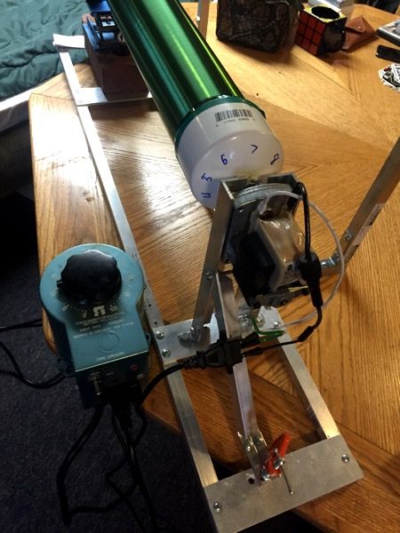
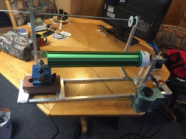
-secondary coil already wound. 1640T 30gmagnet wire.

Tube I have in mind 833C(or A). It's an expensive unit for sure but it will give me an option if I want to build bigger.

Where can I source Quality doorknob capacitors?
The second transformer in the circuit is used to heat the grid filiment 10v, <10Amp AC output. Is it common to just use another mot and rewire the secondary for 10v? I haven't read the data sheet for the 833c for its specific needs. Do those secondaries need to have HV wiring or primary 12awg?

I have only JUST started researching. Things I'll be checking into next are the grid resistor and leak circuit.
Right now I won't build a staccato controller though I understand it's benefits.

Is my secondary coil using 30awg magnet wire insufficient for >500W operations? I'd at least like to achieve 16-20in streamers.
Any thoughts, suggestions, parts fs I'd much appreciate.
Thanks guys!
 
Last edited:
Joined
Dec 11, 2011
Messages
4,364
Points
83
30AWG is fine for up to a kW or so (at most common topload potentials) I've found.

I like the 833A tubes, they're robust but expensive. Good choice.

Yeah you can gut a MOT and make a new secondary from 10g wire for the filament trafo.

Look to ebay for doorknob caps, it's pretty much the only source =/ .


Top