Welcome to Laser Pointer Forums - discuss green laser pointers, blue laser pointers, and all types of lasers

Buy Site Supporter Role (remove some ads) | LPF Donations

Links below open in new window

FrozenGate by Avery

Tesla Coil Build Thread

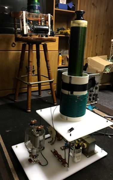
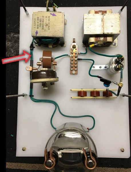
Awwww yeahhh. Here's my parts that have come in and progress.
Dash apple, any comment? I know you have built a few vttcs.
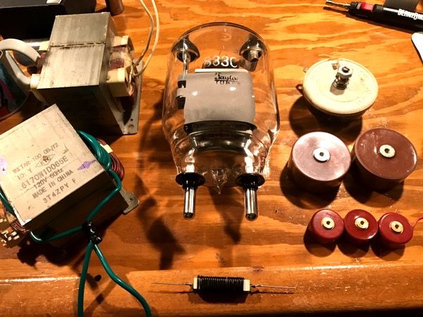
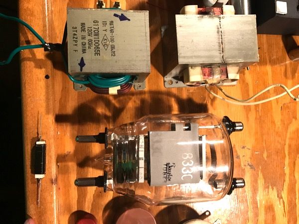
The tube came in! a 833C Taylor tube. I've ordered some 14mm ceramic caps for the grid/plate pins but the filament pins are larger than I expect. .007" to be exact.
-Tank capacitors. 3x .001nf 30kv doorknobs in parallel. I sourced these from amazing1. (I might adjust the configuration as I progress)
-grid leak resistor and capacitor : 5kohm 100W variable resistor. This was a good find.
- grid leak cap: .002nf 40kV door knob.

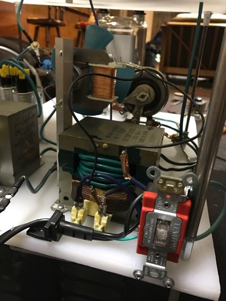
Filament heat power source. Now, someone please advise me on this. The spec sheet for an rca states 10vac 10A. I have wound a MOT with 10awg hook up wire. I get 11.05vac with 10 full turns and 9.86vac with 9T. @ 9 1/2 turns I get 10.5vac. I've have never wound a mot. Is it acceptable to wire the transformer like this? Second, it should be safe to test the filament heater on the tube?

For my primary I have a spool of 10awg. Probably over kill but I have a whole damn spool.

Question number 2. Is there anywhere in the build hv gto wiring is needed?

Item number two. I have two dissimilar hv mot caps one 1.05mfd @ 2100vac and the other at 1mfd @ 2300vac. Not sure how well these will parallel. Combined they don't read on the DMM. Individually they do.
 
Last edited:


good luck : D , just remember these VTTCs arnt self tuning like a antenna SSTC , you have to tune the LC tank primary to the secondary frequency and tune the feedback winding aswell .
 
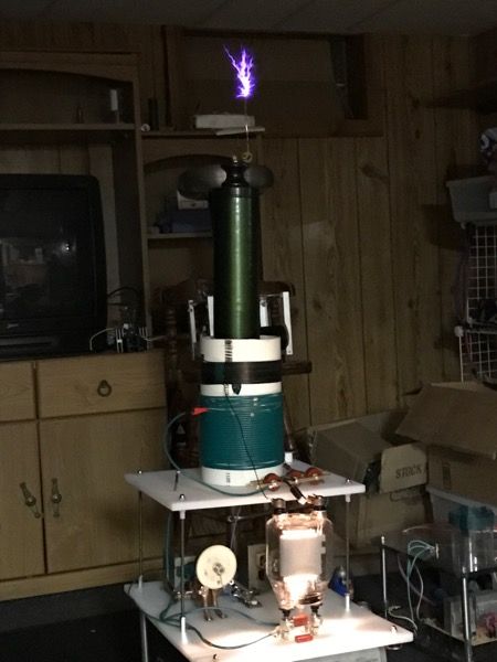
Progress!
Thanks dash, I'll keep that in mind. I know the secondary resonate at 300kHz. The target tuning would be right below that number correct.
I also have an adjustable 5kohm resistor and 2000pf cap to turn the grid leak values. Hmm I started with an arbitrary 28 turns of 22awg around the secondary for feedback.


Oops I forgot to ground the neutral leg of the filament heater. not sure how to determine which lead that is though... well, with the tube out for safety, one will pop the breaker the other won't when shorted to ground. :(


Testing starts soon!
 
Last edited:
Nice work , I would've made the transformer centre taped with the centre tap being the ground , that should work
 
Think I should ground the filament heater on a separate circuit? It will have its own power cord separate from the variac ps.
I apologize for asking a really nieve question but I'm not sure how to determine which secondary leg to ground.
Any suggestions?
 
Oops I forgot to ground the neutral leg of the filament heater. not sure how to determine which lead that is though... well, with the tube out for safety, one will pop the breaker the other won't when shorted to ground. :(

Just pick a lead. None are physically tied to mains so no worries of popping a breaker.

Edit; Yes make the filament a seperate circuit.
 
Last edited:
So, in the video I didn't see the plate in the tube suddenly start to glow. What failed?
 
Ahh, apologies I failed to elaborate it's been a crazy week.
The tube is working great. I popped the rectifier/doubler diode coming right off the mo caps. It failed at approximately 70% power on the variac.
The diode was rated for 1A 20kV and There are 2 ceramic disc caps in parallel across that diode. {might add doorknob here}

Moving forward I used one of the diodes salvaged from the microwaves and just run it at lower power for tuning. Also ordered a more robust diode for full power.
Performance is still very poor that is also another objective that needs to be addressed. I have another mot coming I might try running a duel mot system or punching out shunts and running it in oil.

I tried to add a top load and got this noise! >.< arcing from secondary to feedback coil.


More updates to come.
 
Last edited:
Oooh! Excellent, DWU!

Yeah, VTTCs are highly tuned coils, so adding topload capacitance is tricky. Glad you didn't pop anything expensive, but they do tend to be fairly robust.
 
Tuning is an ongoing process from what I can tell there are three variables here:
1- #of turns tapped on primary
2- #of turns on feedback coil
3- the resistor value in my RC circuit for the grid leak.
It seems to be running stable right now at approximately 325kHz but STILL needs attention.
I have room on my primary conform to disconnect the black hook up wire coil and do maybe 20-25turns of magnets wire.
Other problems are my oscilloscope is having trouble triggering on a clean waveform. That might be operator error though, that's half the fun right?

it's also drawing 16 amps at 75% power!

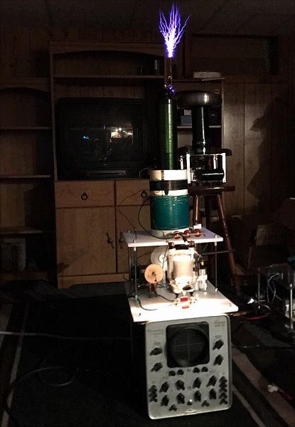
Side note. Using cutting boards are a practical way to build a platform but the white is hittiously ugly
Id like to strip everything but the frame from the god awful oscilloscope and put my parts in there but it would be a really tight fit however quite possible.


Other modifications in an addition of a salvaged microwave fan. And she cranks!

I put a SPST switch in the circuit so I could turn the filament transformer on and off and still allow post cooling.
 
Last edited:
Tuning is an ongoing process from what I can tell there are three variables here:
1- #of turns tapped on primary
2- #of turns on feedback coil
3- the resistor value in my RC circuit for the grid leak.
.

Those are the three main ones you need to look for , remember as you load the secondary the frez will drop detuning it from the primary
 
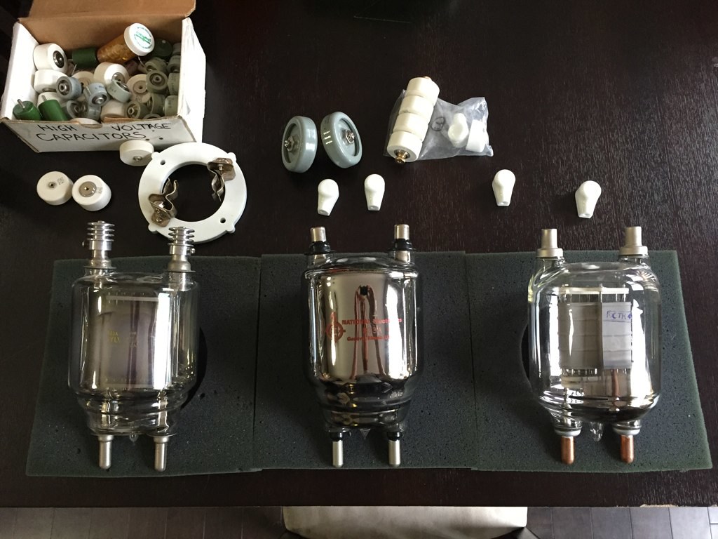
Gathering parts for my VTTC build.
30760825376_33a7d536ed_b.jpg
 
Last edited:
That's quite the stock pile of parts. Have you just accumulated them over the years?
I look forward to your progress.
Are you going to build a duel?
 
I have been slowly acquiring parts for a while now.

Seeing your coil got me motivated to get this project moving.

I'm planning on a single 833A or the GU48.

Now I just need to salvage some old microwaves..


Back
Top