Welcome to Laser Pointer Forums - discuss green laser pointers, blue laser pointers, and all types of lasers

Buy Site Supporter Role (remove some ads) | LPF Donations

Links below open in new window

FrozenGate by Avery

Tesla Coil Build Thread

Thanks :D

Nice , I did want to try something like that with the 2" x 2.2" secondary I had and run it with a boost charging a single storage cap at 400v and plus it at 0.5Hz

I was getting 9.5" arcs from the secondary and low rep rates means I can ditch large heat sinks

Running from a fixed frequency driver worked pritty well , though hard switching was a problem but at the low reps It wasnt a real issue
 
Last edited:


As long as the primary isn't resonant you shouldn't have much trouble with hard switching as long as you use body isolation diodes. That's how I make my bridges so tough, it's all in the diodes.
 
FAIL
this is embarrassing...
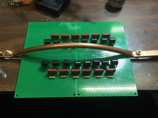
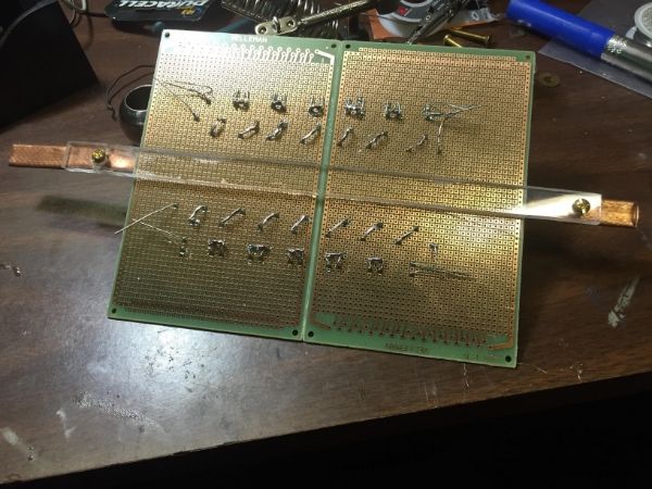
I've Planned this whole tesla coil im building to the T running around buying various supplies on the weekends. well this weekend I decided to build the terry filter. after ordering the components and building a frame and everything I thought I would use two PCB boards I had kicking around. it wasn't until I soldered every thing that I realized....ohh mannn with all these convenient soldering pads the whole board is going to turn into one big arcing mess. (face palm)

the pads are individual but at that voltage they will jump im sure


Last edited:
I guess you could try putting it in oil but the acrylic bar may go funny
 
Last edited:
Hmm my terry filter would be sitting in a little oil tray... would be one of a kind. What if I caked the bottom with some type of potty?
My other option I guess is to painstakingly desolder each component. :/
 
Last edited:
Neither. Those solder pads some right off with a second long hit of a drill bit. Go through and remove the extras. That's what I do!
 
Last edited:
Ahhh, on the entire board there are 3100 pads. I'm thinking of hot glueing around all my connections and using a drill bit to remove one pad at a time in the critical areas.
 
Hot glue is a lousy insulator. Any arcing
will melt it and burn it and make a big
stinky mess. The other problem is that if
you need to make modifications later, the
hot glue will be all over the place
preventing solder from sticking and ruining
your iron tip. You don't have to drill out
all the pads, just the ones near the
connections. If you're still worried, you
can dam them off around the area with a
little RTV silicone.
 
Ya, I didn't mean to imply you have to drill off ALL the unused pads, just two or three out from the connections. Shouldn't take more than an hour at the very most.
 
A dermal with a sandpaper wheel did pretty well at taking off the pads around the perimeter nows it's just around the components. Is there anyway to test the filter without a capacitor bank to kick back a spike?
 
Yeah, just leave the cap off and use the spark gap across the HV lines. You'll still get some RF noise being reflected towards the supply, it's enough to do a flame test.
 
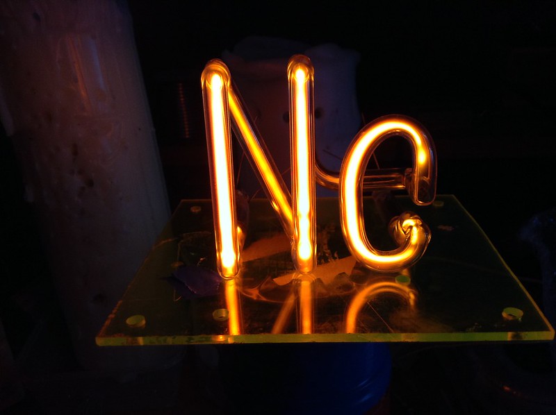
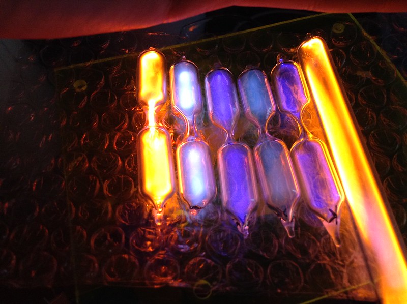
They never quite get the fill pressure right for neon, idk why. It isn't hard to do really, but these Chinese and German made neon tubes just won't fully light.

I've got a small linear Ne with the same problem as yours.

I'd like a fancy H hydrogen one eventually. Nice collection though!
 
here is a review of my SGTC built to date. im building this stages and this is as far as ive gone. Lots more work to do! so far the PFC caps are bolted down, bleed resistors are secured and one NST is bolted everything else can be moved
2x 15kv 30ma NSTs
36 DB .15uF caps (2 strings of 18) 16.7nf
2x 70uF run type PFC cap run in parallel. (Tesla map recommends opt. 166uf)
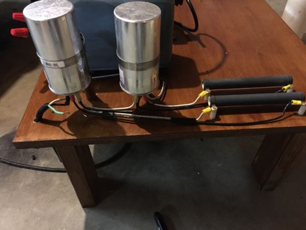
4x 100W 1000ohm resistors. 2 for terry filter, 2 for PFC cap bleed resistors.
4 pair of tungsten rods for primary spark gap.
62cfm PC fan.


not built yet:
4" pvc for secondary W/ 24awg
1/4 tubing for primary.
spark gap not built yet.
Terry filter not connected yet.

So here is my Table. I know most people seem to build their TCs in stacks but for easy access to components and visibility I built mine on this table design. I know this increases the risk of strikes from streamers to my NSTs, caps, and filter but im hoping to mitigate this by building a platform on the table to elevate the primary, secondary coil and top load away from vital components. also the use of a strike ring directly connected to the RF ground.

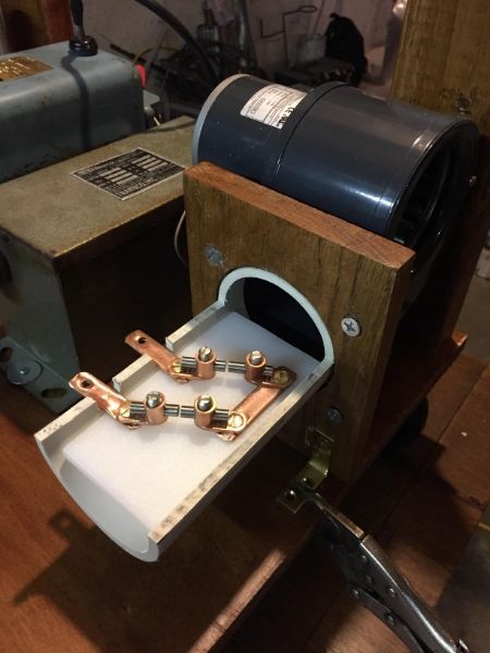
The tungsten spark gap strips are not secure. they will be mounted on the copper strips and be bolted to plexiglass and placed inside a 4" Pvc pipe to maximize quenching.(I plan to spilt the pipe like a clam shell so I can make adjustments to the Tungsten rod gaps then replace the top like a cover to run the TC.

if you can visualize this for me the white box will be a 4x4 a 1' to 1.5' tall supporting a platform made of plexiglass or wood the primary will sit on. I know this is a large design im not really trying to save space.
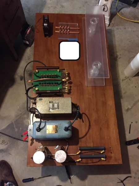

another configuration note also there will be 36 capacitors. pictured is only for display.
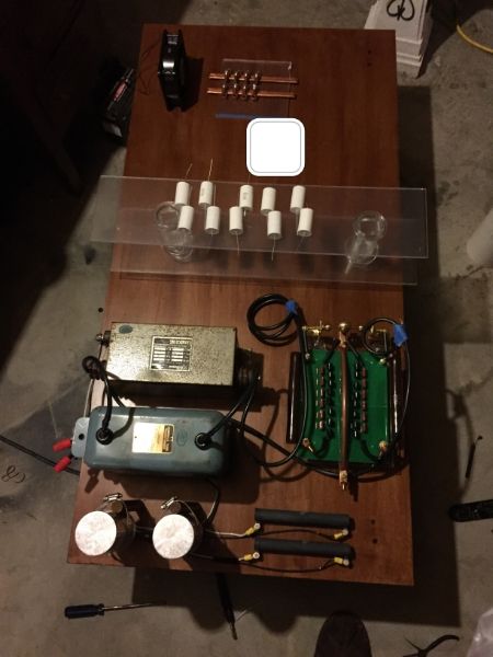

PFC caps are run in parallel each capacitor has its own bleed resistor wired across the terminals. all wiring is 12 awg. HV side is HV 14awg cable.


grounding and high amp wiring: 8 foot copper grounding rod pounded into the backyard. 4awg flexible cable should be able to take the amperage. most connections on this table are brass or copper.

What are your thoughts? how should I change my design? should I secure the NSTs under the table? one concern I have is the bleed resistors are screwed through a nylon spacer to the wood(wood can be conductive). should those screws be replaced with nylon bolts?
I haven't done a flame test but I might this weekend.
thank you:thanks:
 
Last edited:
Check the labels on the PFC caps, they may have internal bleeder resistors (most do). The bleeders you added are only at low voltage (mains) potential, so the mounting with metal to wood is fine. Interesting spark gap design; alignment and setting is going to be a bitch unless you make or have a wide feeler gauge set. You'll need to find an optimal spacing, and then set every parallel gap to that exact spacing. 100microns of alignment error is all that will be needed to cause one gap to fire only and not share load with the others, at which point the others do nothing. With static gaps [not firing] isn't the issue, the issue is it not ceasing to fire (inadequate quenching).
 
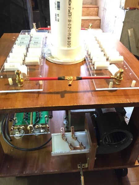
One week at a time...this is where my tesla coil sits right now. I did decide to cut the table and stack to make the most out of my space and also built the capacitor bank and spark gap. for the cap bank I used 6 gauge wiring with copper tubing terminals.

the spark gap I hope will work has a beast of a blower motor I got off ebay and a 4 electrode design. I looked at shop vacs but some were too small or too big and the Dayton blower was in my price range.
My concern is the hardware could rattle loose but the bolts all have brass lock washers and double nuts.


This weekend I will probably assemble the RF ground lead then I should do some flame tests with the terry filter to verify that works.
next I have to come up with an apparatus to secure the primary coil. ugh. I enjoy build this but ill be happy when its done.


Back
Top