Welcome to Laser Pointer Forums - discuss green laser pointers, blue laser pointers, and all types of lasers

Buy Site Supporter Role (remove some ads) | LPF Donations

Links below open in new window

FrozenGate by Avery

Tesla Coil Build Thread

I need a sink like that. May have to go single heat sink with a fan attached to the bottom.


Yeah I got two of those sinks and four of those caps for a steal on 4HV a few years back. Think I paid something like $30. The caps are worth about $100/ea alone.
 
Man thats awesome...I wish I could build one, but a) I have no idea what I would do with it and b) I spend enough money on lasers alone...last thing I need is another thing to dump money into!
 
Do you think the USSTC boards can do
4MHz? I was watching some of zitpopper's
videos, and one in particular of a 4MHz
half-bridge and it looked like something to
maybe attempt someday.
 
You'd have to stack double UCC chips and Heatsink them well, but it can be done. Zilipopper is a madman, I'm sure there's some Russian pixie dust integral to his builds.
 
It looked like he was using some kind of RF
amplifier as a gate driver. It was inside a
shielded RF cage and about the right size
and shape.
 
oops pic. posted first.

I am proud to say I have started to collect parts for my first tesla coil build. I plan on using a spark gap with 4 tungsten electrodes quenched with a DC fan.

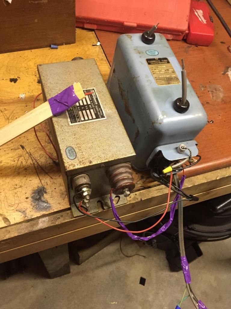
I feel like I got a good deal on two transformers. The local neon sign seller sold me these two for $30 each and threw in 10' of HV silicon wire. we hooked them up to a sign and they both work fine. i haven't decided which ill use. is there a good way to test which one is best?
The blue one is a hanging style Jefferson Electric 15000V 30mA NST pull cord on/off
The gray one is a TRANSCO 15000V 30mA NST
10066-image1.jpg


the coil:
I have been using Tesla map to obtain values and have also referenced JAVATC to get some info.
4in PVC for my secondary 22awg wire.
1/4 copper tubing for my Primary 10 turns
4 x 12 toroid
so far my design is pretty basic. For my MMC I will be using .15uF 942 Caps.
I have a desired capacitance of 8.6nF
I could use 18 wired in series OR 2x banks of 36 to obtain 72kV Plenty of over head for my transformer. hmm big dollar difference here.

as far as a terry filter im not sure where im going to source those parts. haven't really looked at the design yet. I know there is a few pricy kits on ebay I am hesitant to buy.

is Ebay a good place to buy magnetic wire? I need roughly 818 feet.

i just have to say ive loved skimming this thread. lots of talent out there.
 
Last edited:
Terry filters are generally optional as long as you use a parallel gap / series cap circuit. Using the opposite arrangement allows RF to flow into the NST, killing it.

8.6nF looks quite low for capacitance (depending on resonant frequency and physical parameters it can be fine too), so I recommend going over the math you used to achieve that desired value. EDIT: checks out ok but see section on transformers.

Remember you have to impedance match the NST:
DeepFriedNeon - Tesla Coils

And then multiply the value from that calculator by Phi (1.618) to achieve the LTR value you use in the end.

Generally speaking the more paralleled strings of caps in your MMC the more robust the MMC will be against non-overvoltage failure, but I agree, it gets expensive fast.

eBay is fine for magnet wire, make sure it is specified the enamel coat layer thickness and number of coats, try to avoid the jewelry making supply shops. I prefer the Heavy coat stuff, but it does affect the capacitance calculations.

As for your NSTs I'd run them both in parallel for 15kV 60mA total. Just be sure to get the phasing right; you should see no arcing (minor tiny sparking when rubbed is fine from small voltage differentials) between joined nodes. If you have a sacrificial $5 multimeter, measure the voltage between the to-be-joined terminal nodes and it should be <500V. 15/60 NST bank uses a "standard" 17nF MMC arrangement. Note that the easiest to achieve values tend to be around 16.5-17.8nF, all of which work fine. You want >35kV rating for your MMC regardless if you parallel the two transformers or not.
 
Last edited:
Running the two NSTs in parallel doesn't seem like it's going to work. The high voltage output test wire arcs off all terminals After I swap the low voltage leads to hopefully switch phases it still arcs off the opposite terminals. One side more than the other but my cheaper DMM says >500V then flicks off.

If I can't get these to work I might have to pick up a 60ma transformer

The pull cord on the Jefferson effects the transco transformer. When ON I get less output from the transco. It's as if they are not compatible.
(Note the purple tape signals ground wire. )
 
When you say , parallel , do you mean you are running the primary's in parallel ?

The secondary's are centre taped tied to ground , so between the ground and each end of the transformer will be 7.5Kv and 15kv between each end and as both transformers are tied to ground ( I assume you tied the cases to ground ) , depending on phasing 15kv could appear from one terminal on one transformer to the other terminal on the second transformer .

you wont really know if its working till you parallel the outputs from the NSTs together , if the phasing is wrong on the primary , swapping over the HV side phasing or primary will sort it , there will be very little output across the transforms if its wrong , if its right , you will know due to the arc having twice the current ,

The DMM wont give any form of reading on the HV side , if its still working ...


In the picture is the "chicken Stick" red wire connected to the Hv bush on the transformer or the case/ground ?
 
Last edited:
As for your NSTs I'd run them both in parallel for 15kV 60mA total. Just be sure to get the phasing right; you should see no arcing (minor tiny sparking when rubbed is fine from small voltage differentials) between joined nodes. If you have a sacrificial $5 multimeter, measure the voltage between the to-be-joined terminal nodes and it should be <500V
The DMM lives.

Ok so I need to wire up the HV outputs(yes the case is ground) and test for the best arc between the two leads?

Is there any risk of this damaging my transformer?

Edit: haha chicken stick, that's my paint stirer. The other end is connected to the HV bushing. And I used my probe to see which HV terminals are in phase.
 
Last edited:
I can't tell where the wire wrapped most of it's length with purple tape is connected, so I'm not sure exactly what you are doing to check phase of output. You should have the primaries in parallel just as if they were each plugged into separate outlets. Then you could try bringing one end of the blue secondary (with it switched on of course) near one end of the gray secondary. If you get an arc just like you usually see from the secondary of a single nst, then that end of the grey secondary is out of phase, so try bringing the same end of the blue secondary near the opposite grey secondary. If this doesn't have an arc, or it is very weak, then check between those 2 with your DMM. If the difference is small enough then you can parallel the secondaries.

As to your other issue, if both primaries are in parallel and you get less"output" from the grey NST when turning the blue one on, then you are likely drawing enough current at that point to get a significant voltage drop in your supply wiring. What gauge are you using?
 
Last edited:
The wire with the purple tape is my ground connected to both cases of the transformer from the house ground.

Those wires are 22gauge silicon wires...could be chocking the voltage. Tomorrow I'll get some proper wires and try reworking it. I'll report back


Back
Top