Welcome to Laser Pointer Forums - discuss green laser pointers, blue laser pointers, and all types of lasers

Buy Site Supporter Role (remove some ads) | LPF Donations

Links below open in new window

FrozenGate by Avery

Tesla Coil Build Thread

First off; it is possible the center taps inside the transformers are bad and a case is floating, this isn't uncommon.

You won't damage anything by having them out of phase, these transformers are built to literally handle a short on the secondary side 24/7/365.

The pragmatic approach works fine too: Primaries in parallel; parallel up the secondaries, see if you have arc between the two secondary pairs. If no arc, it is out of phase. If larger/whiter arc than a single NST alone, you are in phase.

I'd disconnect the ground/case wire from both NSTs for the time being. Once you have verified phasing with chicken stick safety, then worry about grounding. You can't bond the NST grounds to the Tesla Coil grounds in the finished coil anyway; most ppl just leave them floating.


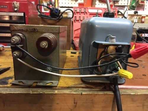
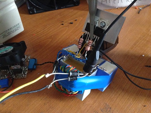
Ok so good new. These transformers appear to be in phase and parallel. I beefed up all the wiring with 12awg. The chicken stick lead is a 18awg HV cable.
Now when I pull the cord on the blue transformer it shuts them both off. In the future I might remove the switch all together but for now it can stay. (Sorry for the size photobucket is being fussy today)


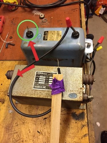
When I touch the chicken wire to the right HV terminal(opposite side the red arrows) I get no spark but when tested with a DMM I do have an OL reading. No spark must mean it's low enough to proceed?
Another question. that short lead circled in green, What's the best way to splice that? What I plan to do is use a crimp and tape the hell out of it. My other option is a high dollar brass splice with heat shrink tubing. My concern is it might arc to the case. (However Right now it doesn't)

Moving forward. Connect the corresponding phase HV outputs and I should be good. Is there anyway I'm able to verify 60ma?
 
Last edited:
You have to connect both leads, parallel,
remember? When you connect the second
lead, there has to be little or no spark.

For splice, you can solder the wires together
and put 2-3 layers of heat shrink over it.

To measure current, connect a clamp meter
and short the output.
 
You don't actually have to verify the current at all, it is about impedances, not actually current levels. Doesn't hurt but doesn't gain you anything either.

In the photo with the chicken stick; touching the chicken stick wire to the circled lead should produce an arc about 15mm long (as in it initiates at a distance around 15mm, you can "stretch" the initiated arc a long way). This verifies the blue transformer is working ok.

Touching it to the point with the arrows won't do anything. What you should do is connect the chicken stick lead to the output terminal on the right (near the inputs) of the gray transformer. Now see if there is arcing between the two not-connected-in-that-picture terminals, the two terminals with arrows pointing to them. There should not be a significant spark here. If there isn't a significant spark, now you try shorting one of the transformer's outputs with a chicken stick.
 
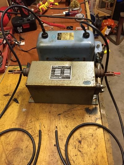
Wired like so. Let's assume the two alligator clips aren't there and the two leads are wired in. I was going to remove a bit of insulation, loop it around the lug sandwiched between two brass washers.
 
Like this:

cTWjoTk.png


Right?

It's hard to tell from the photo if the lower NST is connected.
 
Last edited:
Alright, thank you guys very much the transformers are in parallel. I tested them with a Jacobs ladder and I definitely get twice the spark.
So far I have my AC line filter and switch wired in. Yesterday I got a great deal on 1/4 copper tubing for my primary 50' for $50 bucks(way more than I need but ill use it somewhere). Still need a PFC cap. And the search for good priced 942s continues.
 
Last edited:
You can use beer bottle salt water caps in the mean time. They're super low efficiency, but you can make them almost free. The Geek Group has a few videos on their production. Basically you fill beer bottles 80% of the way up with concentrated saline solution, place them in a tub/bucket, and fill the tub up with the solution almost to the same level the bottles are filled to. Then place one wire in each bottle and bundle the ends together. Place several wires in the tub spaced apart, and bundle them together. You have your two capacitor leads now. Just add/subtract bottles to adjust capacitance.
 
I've been meaning to do a video on my glass
plate capacitors, but can't seem to find the
time/energy. I'm not sure how good they
would be for Tesla coils, though, but they
are fun to play with. Just be careful, they
are NOT toys!

They are basically nothing more than a piece
of thin picture frame glass with a piece of
gutter flashing stuck to either side. There
needs to be a gap around the edge to
prevent flashover. They produce some
pretty wicked arcs, especially when they are
connected to an NST.
 
Salt water caps are usually not lethal since they self-discharge relatively quickly. Glass plate caps will kill ya! They are fun though, made some Al foil ones a year or two ago. The dielectric stress was enough to break a panel and it arc'd internally.
 
I've got the caps for my MMC ordered but I might build a glass plate cap or beer bottles just to experiment with. I'll be cautious with them. Its amazing how you can get such an arc out of a saline solution. Then I see video of sodium and water reactions and am equally impressed. Ahh off topic.

Regarding that PFC cap. A lot of the "run" caps I've been able to get locally are rated for 377V 50uF(map recommends 166uF) I'll be using an input of 120ac. Will that matter?
Also does it matter where I mount the PFC. Right at the transformer or 8' away in a power box where I have the switch and AC line filter.
 
Right at the transformers yields better results, but it doesn't really matter all that much. Get up to the value recommended by the calculator, any helps, and having too little doesn't hurt more than having none. As long as the cap rating is above the voltage applied you're fine, just don't do the reverse. Two of those 377V 50uF caps in parallel would do nicely.
 
Last edited:
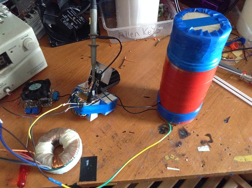
Very nice little coil! Looks like a baby version of the coils I usually make. One of these days I'd like to make a truly tiny one with a professional looking housing that runs on some 3S LiPos and a boost converter to 50V, with a full bridge inverter section. Would make a really nice portable coil.


Back
Top