Welcome to Laser Pointer Forums - discuss green laser pointers, blue laser pointers, and all types of lasers

Buy Site Supporter Role (remove some ads) | LPF Donations

Links below open in new window

FrozenGate by Avery

Tesla Coil Build Thread

ugh. I enjoy build this but ill be happy when its done.

Welcome to the world of Tesla Coiling!

Seriously though, this feeling is the best and worst part of it. It never freaking ends either because as soon as you finish one, you tend to start another. One day I'll get around to finishing my big coil.

In the mean time I've been working on debugging Fiddy's plasma speaker coil.


Oy vey, debugging a plasma speaker sounds tedious. What do you have for an O-scope?

I haven't event got to my secondary yet. I have 1.5lbs of that green 24AWG magnet wire. I'm aiming for a winding height of 23inches according to the map program I should have just enough for 1016turns. (Conform 4"pvc OD just a hair under 4.5in)
With any luck I will be done next month if I can use the lathe at work.
 
Oy vey, debugging a plasma speaker sounds tedious. What do you have for an O-scope?

Just an old Goldstar OS-7040 40MHz Analog CRO w/ wideband Current Probe, 2kV HV probe, and 2x standard probes. It's 2ch, and I don't have a differential probe so it makes it a headache to take differential measurements since I have to use both channels to do so.

This plasma speaker isn't so bad, I'm mostly seeing the inherent flaws of the 4046PLL's phase comparators. There's good reason why all the innovators have stopped using this chip. Tons of documentation on it on 4HV. The short of it is that when used in TCs these PLL chips have a bad habit of blindly running back and force across the entire VCO range when the PhComp can't get a lock on the signal. The larger issue is that there is no formula for the VCO frequency of a 4046 PLL. All anyone has to work from is an old low res blurry graph of frequency, voltage, R, and C values for the timing network that have to be interpolated across to get any semblance of useable approximate data. Basically the only issues with Fiddy's design is one capacitor and one resistor are not the right value for a PLL lock. I've changed the cap and gotten stable operation, but I need to change the ratio and amplitude of the two resistors in the timing network to adjust the lock range within the VCO range so that more of the adjustment range on the pot is useful, and so that the pot isn't so twitchy. It's a long process of trying out various values of R and C while monitoring frequency response of the system.

I may make a video of it running first showing the frequency response. As it is right now with just the adjusted C, you can clearly see both Upper Pole and Lower Pole operation, as well as first and second harmonic drive operation.

If I had to nail down a single issue with it right now that is of priority it would be that the PLL lock maintenance range is lower than the PLL lock acquisition range, and both are lower than the bandwidth of the resonator's two poles. So once locked and in tune environmental changes will detune out of the maintenance range and then the PLL loses lock. Then the PLL tries to get lock back by swinging wildly across the VCO range and locks on to a harmonic instead of a fundamental. It's a simple and well documented problem, really. The user end fix is to re-tweak the phase adjustment and tuning pot. The designer fix is to adjust the RC network until more lock durability is achieved.

When you look at the whole picture you're left with two conclusions for improvements; go with a feedback-less VCO based system for Hi-Fi Audio Modulation ("Plasma Speakers") like I have with my own coils, or go the high tech route of an entirely digital PLL like the "masters" (Conner, Ward, Goodchild, Burnett etc) have.
 
Oy vey, debugging a plasma speaker sounds tedious. What do you have for an O-scope?

I have a Rigol DS1102E. Though the DS1052E
is more than enough for Tesla coil
troubleshooting. For line isolation, I
have a 1000W HF inverter, which is pretty
noisy. It doesn't matter much though on
simpler stuff that runs at higher
voltages. There are much better ones on
the market, but they cost more.

You can also buy an isolation transformer
or make one from an old microwave
transformer.
 
Last edited:
Thanks for the info on the o-scope. I might tune a tesla coil or possibly use it to scope some drivers I'm curious about.
Im on the fence about getting one because im not sure how much I will actually use it. If I did it would be in the $200-300 range that seems to be on the low end but not the cheapest on ebay.

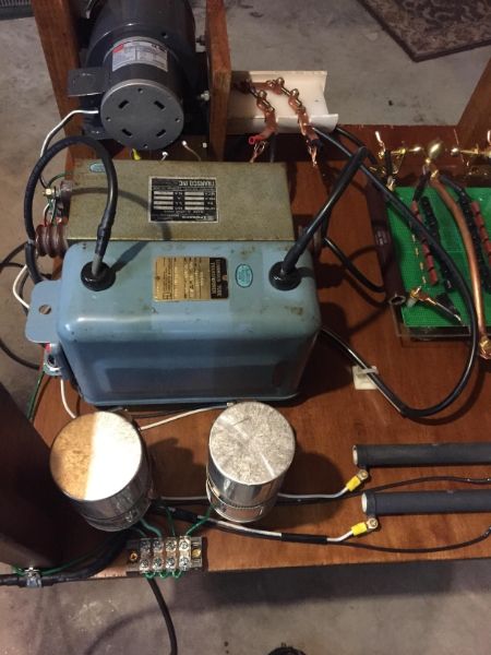
Soo grounding this beast. everything on the chassis is ground to two locations. the strike ring, terry filter, and secondary will go right to the RF earth ground.
however my blower, NSTs, and Capacitors go to the mains ground.


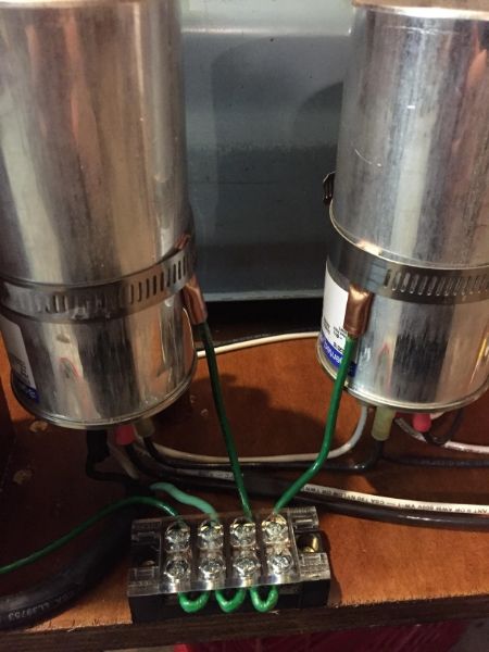
On these caps there is no designed grounding point. What do you think of this idea? im hoping the strike ring will do its job but ahh, I haven't built one before so well see.

 
Last edited:
What you've done with the caps looks perfectly fine to me. It isn't going to be conducting any current normally, it's just to keep it from floating, and prevent any RF from wanting to go -through- the cap in the event of a strike.

Any timeline for when you expect to do a first light? I'm anxious to see it running!
 
I'd like to wrap this project up by mid December but I have been working long hours at work + travel.

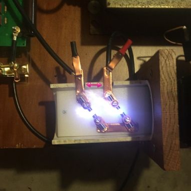
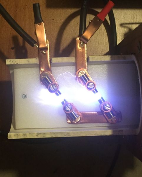
So I've used a caliper and after lots of adjustments ive found .250in the gaps(each gap has .25in) wont quite fire unless I turn on the blower. HOWEVER, I might have gone over kill on the blower.. My reason for buying such a large blower was because I was only using 4 tungsten electrodes and I wanted to keep them cool and quenched but as the gap widened the arc started to wander.
NOTE its not a solid arc but every few seconds it would flash over to the other electrode as seen with red arrows.

few options.

first option would be spreading the terminals further apart. I tried using a quick barrier but it just arc across diagonally to the adjacent terminal.

second would be using a fan with a lower CFM.
without a variac is there anyway to dial down the blower?

ideas?

 
Last edited:
Gotta spread them. This is one of the reasons I don't like series gaps, btw (too many variables). I'd move one of the entrance posts so that instead of the gap being
\ _ \
it is \ _ /


Oh, and don't change the blower. Trust me, when you get capacitance behind that gap, you'll need as much cfm as you can cram into it.
 
Why have two spark gaps in series instead of one wider one?

If two is the way to go, electrical tape might help.
 
Last edited:
Why have two spark gaps in series instead of one wider one?

If two is the way to go, electrical tape might help.

Two gaps reduces the chances of thermionically induced power-arcing by spreading out the conduction surfaces over more material and surface area. It also doubles the chances of a failure to strike (bad), and increases the losses in the system (again, bad). I've used a single gap in all of my SG coils, but electrode cooling, thermionic emission, and quenching were always issues I had to contend with. Not to mention electrode ablation. For a NST powered coil though, most, if not all of those issues are still tackable though. It's only when you get into the MOT and Pig powered coils that you really need to either use beefy series gaps or move to a RSG.

Inherently there's no "harm" in the gap arcing across the I/O out of the SG module, at least electrically speaking. A power arc or short-distance arc are both safe events, they just eat tons of power and reduce output. A failure to arc is the dangerous situation because it can allow resonant rise to destroy the tank cap and possibly the NSTs (unlikely with a TF and safety gap though). The only issue is one of safety - arcing at the wires leads to fires. Quick, someone make a 1950s style public safety placard out of that, haha!
 
If two is the way to go, electrical tape might help.
I considered the idea of taping one of the terminals but I'm afraid it might get hot and sticky. I tried to use the biggest heat shrink tubing I have but it wasn't big enough to cover the tungsten set screws.

I'll pull the SG platform, re configure the set up and see where that gets me.
If I can get the SG tonight tomorrow I might start cutting material for my primary coil.
 
TLS thanks for the heads up on the TRIAC dimmer I'll keep an eye out for them. To build a barrier I got some one inch PVC I might cut laterally and place over the terminal set screws.

UPDATE I used this configuration \_/ only at a right angle and it works great, no random arc flash over. Problem though, now when I cycle on and off my NSTs they sometimes Fire and sometimes they don't..blower on or off. All the wiring is good. No different than yesterday except the gap.
I know NSTs are designed to take a short but I'm just perplexed as to why this would happen now. I shortened the gap slightly and it still is intermittently start up. I hope I haven't broken them:/.


Back
Top