Welcome to Laser Pointer Forums - discuss green laser pointers, blue laser pointers, and all types of lasers

LPF Donation via Stripe | LPF Donation - Other Methods

Links below open in new window

ArcticMyst Security by Avery

Tesla Coil Build Thread

Joined
Dec 11, 2011
Messages
4,364
Points
83
Nah you didn't break them. Small changes in air density and particulates change the ionization threshold of the gap. Just close the gap gradually until you get reliable operation. Once you get a running coil fine tuning is easy.


Joined
Aug 16, 2013
Messages
971
Points
43
Right now it's behaving pretty particular.
Note I've closed the gap quite a bit. Was .250 now .175in.

It runs steady without the blower.

Turn blower on it runs for 25 seconds then starts to flicker then extinguishes after a few seconds it will flicker some more.
One variable is the flat surface of the end of the electrode. It has been breaking off the top edge blower off. Blower on it breaks off around the face of the electrode. Hm

It's possible this would have happened with the other configuration but I just didn't run it that long. I do have four 5/8s brass balls but I feel that would be a step back at this point.
 
Joined
Dec 11, 2011
Messages
4,364
Points
83
For 5/8" spheres the total gap should be about 0.35". Altered of course by pressure, humidity, air particulate levels, etc.

For flat electrodes with rounded edges the total gap should be about 1.1".

Remember to set the gap without the blower running.

Again, when the coil is running it is easy to see. Too closed just eats power and runs at a lower power level, the sound of the gap gives clear status of it's spacing too.
 

USAbro

0
Joined
Oct 16, 2014
Messages
1,006
Points
0
Hey guys. Got a question about the tesla coils. If I am powering a secondary of 2 inch pvc with 500' of 28 AWG wire, with a primary of 5 wraps flat at the base of 10 AWG wire, and powering it with a flyback powered by a lamp ballast, powered by 120 volts then wire are the secondary sparks only 1 cm. There less impressive then the flyback by itself. Is the problem the flyback? Am I powering it with too little current or voltage?
thx in advance.

edit: flyback is putting out 1.5 cm long sparks/arcs. I have two leyden jar capacitors and a spark gap. The widest I can make the spark gap still spark is 2mm. The wires must get close to start the arc.
How much would it cost to power it with the mosfets/transistors?
 
Last edited:
Joined
Dec 11, 2011
Messages
4,364
Points
83
USAbro the reason you are getting shitty performance is that you are missing out on one of the core aspects of a SGTC; impedance matching the power supply to the LC tank circuit.

That is, of course, assuming you are actually tuning the primary so that it is resonant. I'm not even sure you're doing that, and if that is the case, you've essentially failed at making a true tesla coil; all you've made is a spark gap switched step up transformer. Just because it looks like a tesla coil, and has many of the parts of a tesla coil, does not make it a tesla coil. By definition they are resonant air-cored transformers. If you aren't *oscillating the primary* at the secondary's resonant frequency, it isn't a TC.
 

USAbro

0
Joined
Oct 16, 2014
Messages
1,006
Points
0
Can someone help me figure out how to make it resonate? Do you think a flyback is enough to power it?
Any ideas on how to tune the coil?
 
Last edited:

nospin

0
Joined
Feb 13, 2010
Messages
182
Points
0
Can someone help me figure out how to make it resonate? Do you think a flyback is enough to power it?
Any ideas on how to tune the coil?

Forget the flyback, that secondary would be impressive with a 15k 30ma NST
What do you have for a cap and topload?
 
Joined
Aug 14, 2013
Messages
2,655
Points
63
Flybacks aren't much good for driving a TC
because not long after it begins to work,
the diode stack blows out from all the
energies flying around. Then you basically
have an AC flyback and the tank cap begins
to just act like a short circuit. You need
a big iron neon sign transformer or
something else that runs at a low enough
frequency to charge the cap.
 

USAbro

0
Joined
Oct 16, 2014
Messages
1,006
Points
0
Using a 9kv flyback. I've got two layden jars with aluminum tape on both side (inside and out) in parallel. They give huge sparks and create a good frequency and the flyback hasn't died yet, but I may need to lay my hands on a nst.
Also the fact that I'm driving the flyback with a lamp ballast doesn't help.
Maybe I'll post some images when I get some time and show you all what I'm working with. The cheapest NST on ebay is $50, too much for my budget right now.
Any other cool ideas of what to do with the flyback I got? It produces 1.5cm arcs.

edit: Oh and this paticualar model of flyback puts out about 8ma at 9kv.
 
Last edited:
Joined
Dec 11, 2011
Messages
4,364
Points
83
Unless you've actually measured the output of your flyback, you have no idea what it is outputting in terms of open circuit voltage or short circuit current. That's rule no1 of hobbyist flyback use.

I've got a "15kV" flyback on my shelf that outputs 72kV open circuit from 12v input. Just an example.

You can use a DC flyback for a SGTC but you need a series charging inductor and basically have to follow the "dc resonant charging" scheme pioneered by the SGTC veterans on the TCML. Google what I put in quotes in the prev. sentence and you'll find the how-tos.

You make the primary resonant by knowing/measuring the capacitance of your tank cap(s) and modeling the primary on a program such as JavaTC to get the inductance, then find the resonant frequency of your tank circuit. Tune the primary by adding or removing fractions of a turn to get it resonant at the same frequency of your secondary.

You can make a 5W or 5kW SGTC perform well, it's all about impedance matching the power supply transformer and tuning the primary to secondary resonance.
 

USAbro

0
Joined
Oct 16, 2014
Messages
1,006
Points
0
Oh cool I didn't know that about the voltage. I used a high voltage meter (the kind with a needle) to measure the voltage.

You really helped a lot :)
 

nospin

0
Joined
Feb 13, 2010
Messages
182
Points
0
I'd like to wrap this project up by mid December but I have been working long hours at work + travel.

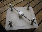
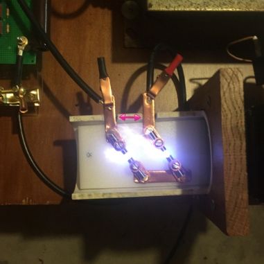
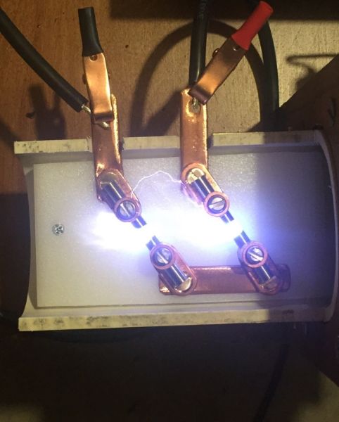
So I've used a caliper and after lots of adjustments ive found .250in the gaps(each gap has .25in) wont quite fire unless I turn on the blower. HOWEVER, I might have gone over kill on the blower.. My reason for buying such a large blower was because I was only using 4 tungsten electrodes and I wanted to keep them cool and quenched but as the gap widened the arc started to wander.
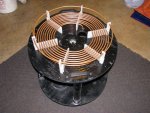
NOTE its not a solid arc but every few seconds it would flash over to the other electrode as seen with red arrows.

few options.

first option would be spreading the terminals further apart. I tried using a quick barrier but it just arc across diagonally to the adjacent terminal.

second would be using a fan with a lower CFM.
without a variac is there anyway to dial down the blower?

ideas?


Here is what I built and it is the best spark gap I have seen
my results speak volumes

It features a 7" rotor and 4 breaks per revolution
I has 1/4 inch tungsten rods all around and is driven by a
free vacuum motor on a small variac

I gives you the capability to interact with the power line frequency
to get the most out of your setup

and lose the PFC cap resistors those are counter productive
 

Attachments

  • IMG_3114.JPG
    IMG_3114.JPG
    168.9 KB · Views: 93
  • IMG_3113.JPG
    IMG_3113.JPG
    163.2 KB · Views: 91
Last edited:
Joined
Aug 16, 2013
Messages
971
Points
43
Here is what I built and it is the best spark gap I have seen
my results speak volumes

It features a 7" rotor and 4 breaks per revolution
I has 1/4 inch tungsten rods all around and is driven by a
free vacuum motor on a small variac

I gives you the capability to interact with the power line frequency
to get the most out of your setup

and lose the PFC cap resistors those are counter productive

Nospin, that is an awesome looking Rotary gap. Eventually I will probably build one just like that but or right now I think ill stick with the static gap because my MMC is already built for this gap.


Also, I'm sure you know more about this than I do but where would those capacitors bleed off too? those resistors in parallel are they some how choking my low voltage input?
here is a link to their datasheet.
http://www.farnell.com/datasheets/1788386.pdf

I am on a ROLL this week :crackup:
Here is my primary. I bought a 50' roll of 1/4" copper tubing and I admit in the beginning I wasn't sure how it would turn out.
the 1/4" spacing is drilled into an oak brace. Initially I had intended to feed it through but I gave up on that pretty fast and used zip ties. There is 6 1/2" inches between the first turns and the OD of my pipe is roughy 4 1/4. So that's an inch and an eighth of space all around.
the first turn and oak block ends are sandwiched between two cutting board cut out rings. there are about 11 turns and the strike ring end will go right down to the RF earth ground bus on one of the legs.


Now you can't see it in the photo but the first turn is turned down and will connect to my spark gap.
My flexible 4gauage lead will connect to my tap point if I read the schematic correctly. I have seen people use 1/4in fuse holders for the connection but I could flatten some more copper for a clamp.
As far as coupling the primary and secondary I plan on trying to make the secondary height adjustable.

Also I need your thoughts on the Cap bank location. Is it going to interfere with the primary? from the top of the capacitors to the bottom of the primary is 6 inches. Personally I think it is aesthetically pleasing to see but it could be mounted on the underside of the table.

thanks guys.
 
Last edited:

nospin

0
Joined
Feb 13, 2010
Messages
182
Points
0
Wow I think it looks great!

Your tubing, spacing, and height adjustability, is the same route I went with
my coil.

strike rail to RFGND looks great!

and those PFC caps are across the primary of your NST bank so its built in, no need.
They would however catch on fire as you made a Vienna sausage cooker instead!

make your own clamp and you should make a Faraday cage to protect the caps and everything else
It will reach around!

How long of an arc are you able to draw with your NST bank?

and how many nf is your cap and at what rating?

Here is my primary V2 as I'm moving to a 6.6 inch secondary from the
4.25 inch I built 4 years ago

And I upgraded the gap with a 1/4 rotor up from 1/8 inch
 

Attachments

  • 00.jpg
    00.jpg
    107.7 KB · Views: 68
  • 01.jpg
    01.jpg
    62.5 KB · Views: 120
Last edited:
Joined
Aug 16, 2013
Messages
971
Points
43
and those PFC caps are across the primary of your NST bank so its built in, no need.
They would however catch on fire as you made a Vienna sausage cooker instead!

How long of an arc are you able to draw with your NST bank?

and how many nf is your cap and at what rating?

Here is my primary V2 as I'm moving to a 6.6 inch secondary from the
4.25 inch I built 4 years ago

And I upgraded the gap with a 1/4 rotor up from 1/8 inch

That 6,6 in coil your building is going to be a beast. The photo in your signature is epic!

I Remember reading in an earlier Atomixrox's thread entitled Mains Grounding
The low voltage Neutral wiring is tied across the mains ground. :thinking: can't seem to find that url. But that I suppose would bleed it off.

My cap bank value is about 17.5nf. To achieve this I have 2 strings of 18 DB .15uf caps. Each cap is rated 2000v so I should have a total of 38kV.

This week I plan to wind my secondary. Winding hight 22 inches of 24AWG magnet wire.
It's a work in progress.


Top