Welcome to Laser Pointer Forums - discuss green laser pointers, blue laser pointers, and all types of lasers

Buy Site Supporter Role (remove some ads) | LPF Donations

Links below open in new window

FrozenGate by Avery

Tesla Coil Build Thread


If you want to ballpark it then measure the input current and output voltage (unloaded/ open circuit) and use that to determine the stepdown ratio:

If primary is 120V and you are getting 1.2V out open circuit on the secondary, then you have a step down ratio of 100:1. Short circuited you are drawing 10amps on primary so multiply your input current by 100 to get output current. You'd be getting ~1000A at the secondary. This only works for a ballpark figure though.
 
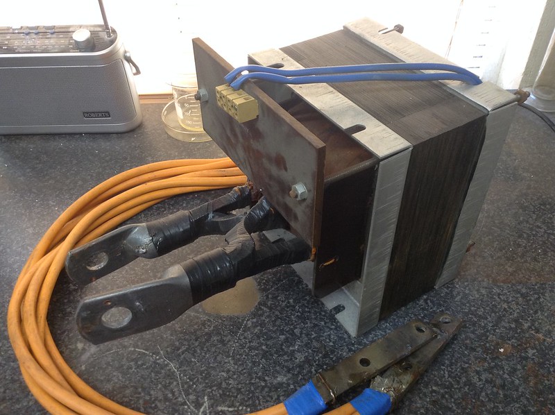
High current is fun : D , Scored this a while back , Ive pushed 5Kw so far with this transformer , output voltage is 3.6 Volts . Its rated for 450 Amps continuous but is capable of way more than that :P

At around 900 Amps its melted 150mm x 10mm steel bar .

IMG_0428[1] by TwirlyWhirly555, on Flickr
 
Last edited:
Does anyone know a good source of HV fast diodes? I saw some on eBay, but they are charging 5x what
they're worth.

Seen many for sale in South Korea,
Do you have any diode descriptions example: FR607 1KVdc

I think these are reasonable (less than 500W for 4 diodes)

:thinking:

let me know as I have a favourite store for HV diodes :san:
 
Last edited:
Ideally, they would be like 5 - 10kV <500ns recovery time, the current doesn't have to be anything
spectacular, like not even 100mA. I was trying to use the diode built into a flyback transformer, but the
inverter on the input is a 2 transistor SLR and doesn't like having half the phase swinging unloaded. With
that approach it would take 4 flybacks to build a bridge, and they are getting in short supply these days.

hmm I'll take a look and see what we've got locally.
There were some 5Kv diodes available awhile ago, but those aren't used anymore.

If you've got a part number of a diode you're looking for then that might help.
like this SMF6529, or 1N6529?
 
Update on the two coils that are in progress.

BGS:

Got all my MOT's and wired them up in a wooden box that will sit under the coil. ~4.5kv at 1A.

Open at both ends for airflow. MOT up front is my ballast.


120V input.


HV output


Got some nice warning signs :) I plan to add some sort of key switch if I can find one that can handle the power and then a rectified board to power a buzzer to give me a audible warning the box is hot. I'm not stupid but alcohol is usually involved when working on these type of things lol


USSTCC:

Conical secondary wound and topload secured with a nylon screw. Just need to attach the secondary to the topload and add a breakout point. Still hunting down heat sinks for my bridge.


This coil has its fair share of gaps. Its quite difficult to get wire to stay flush to each other on a slope. No overlaps though.


Baby powered coil was a flop. I don't think the baby is supplying enough power. May need to switch over to a two baby set up :)
 
Hehe, careful with the multiple baby setups; maintenance costs are through the roof!
 
Good output,


Some safety points you might want to consider,

I'd seriously be considering protecting the output HV wire with some PE / Vinyl wine tubing OR make some insulators for your HV supply!


You also might want to think about using a piece of large Polypropylene cutting board instead of the wood as your output area.
IF that insulation breaks down in higher humdity levels (had it happen to me on a table) you'll be creating (carbon tracking) which will lead to a fire.

I strongly recommend the PP cutting board route!!
 
Last edited:
Does the whole thing need to be cutting board or just the top piece? The base of my coil will sit on top of this and the hv wires will go around to the the base and connect to the rsg so the top should be completely away from any hv except where it exits the box. I'll have to get some of that tubing and double insulate it inside the box and where it exits. Single insulated to the rsg to make it easy to connect and disconnect.
 
Does the whole thing need to be cutting board or just the top piece? The base of my coil will sit on top of this and the hv wires will go around to the the base and connect to the rsg so the top should be completely away from any hv except where it exits the box. I'll have to get some of that tubing and double insulate it inside the box and where it exits. Single insulated to the rsg to make it easy to connect and disconnect.

No, the exit hole where the HV terminates is where you'd want the PP cutting board. That whole panel needs to be PP to keep your setup safe.
Further more, insulate the wire with Vinyl tubing from the XMFR output as well.
 
Found some pp sheets 1/4 inch thick on the bay. Good price and size. May get a couple and use that for my rsg. Couple questions though.

When screw get the pp together in the spark gap area can I use metal screws? Or is there some other method I should use to secure cut pieces together.

How do I build HV terminals? It would be neat to have two nst style terminals back on the back so I can just bolt on either the coil or whatever I want to fry. I see some on the bay but if they can be made cheaper I'llgo that route .

1) I'd be not using PP or PE anywhere around your RSG, as PP will easily succumb to heating (burns rather like wax). Building an RSG requires VERY a very thick base/ heavy due to the vibrations and (kick) made by the motor. You're going to want to look at Phenolic for your RSG (disk) and Oak ( or something with mass) for your base. Phenolic ain't cheap either.

2) The electrodes on your disk can be made from copper but the contact points should be made from large dia WZr welding (cutting) electrodes. You must make sure these have a (non radioactive symbol on them). Avoid Thoridated electrodes.

3) You must always make sure that the electrodes on the disk are secured with some sort of dual lock nut... The disk will be spinning at 2-300Km/hr (3600RPM) and the last think you want is flying electrode bullets!! If these hit you, they can seriously injure or kill you or someone else.
I used a double lock nut on mine.

4) You must make sure your RSG motor can handle a heavy shaft load.

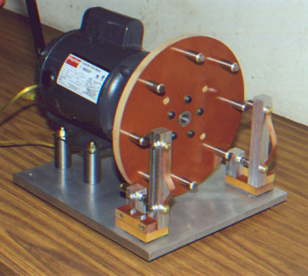
I've posted a few pics to show you some set ups.. .you'll notice that most are using metal bases (floor plates)

you'll notice below the RSG is using many contact points.... This is an example of a Synchronous RSG. These motors are rare, or they have been modified to
be in sync as the supply current. These are ideal but not completely necessary.

rsgfront.jpg


This is a basic setup using an cheap angle grinder.
This is an Asynchronous setup using 4 precisely spaced electrodes.

I have done business with Greg in the past while building my last big coil.
I do not recommend using brass for your electrodes as they will burn down quickly despite Greg's experience at 10KRPM. I'd seriously consider
a heavy base. Vibrations from angle grinders can throw the electrodes out of alignment. So a heavy base will dampen this effect.


rotary1.jpg


There are pros and cons of using Asynchronous and Synchronous motors
in an RSG.


  1. Synchronous rotary gap

    1) Firing rate is fixed at the design stage
    2) The system should be designed to be optimal at the synchronous firing
    3) Requires an induction motor to be modified for salient pole, synchronous rate
    4) Requires firing phase to be carefully set for correct operation
    5) Produces more consistent, slow methodical evolving sparks
    6) Good power throughput with large ballast inductance.
    7) Peak voltage stays constant because resonant rise is kept under control
    (ok for multiple NSTs banks!!)

    8) No beating because operation is synchronous with the supply frequency
    9) Ideal for analysis and taking measurements


  • Asynchronous rotary gap

    1) A wide range of firing rates are possible for flexibility during experimentation
    2) The optimal operating point of the system can be found by varying the firing rate
    3) Easy to build, can use any general purpose AC or DC motor (including angle grinders!! hint)
    4) No special set-up is required
    5) Produces frantic spark action, with frequent long sparks (emphasis on erratic!!)
    6) Requires low ballast inductance, particularly at high speed. (This implies higher fault currents.)
    7) Can cause damaging resonant rise in charging circuit, (particularly at speeds below 200bps. Stay above 200BPS) (Don't use this for NSTs or you'll kill them!)
    8) Can give surging/beating problems below 200bps
    9)Rotary speed can be used to control power throughput in DC powered systems (N/A in your situation)

This information was taken from
Rotary spark gap overview
and I added a little to it.

My personal experience with RSGs has been variable. Heavy bases are HIGHLY recommended due to motor vibration.
Brass does not work well for electrodes.. WZr is the best material.
Keep your RSG away from your coil until you've got it working. Last thing you want is a flying electrode to damage your tank cap or secondary!!


Hope this info helps you!!
 
Last edited:
Nice SGTC work : D ,

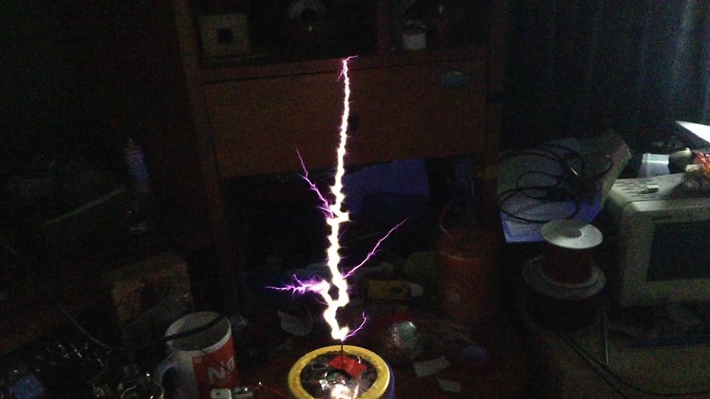
I've pushed my 2"x6" secondary and the tube further today , confirmed strikes to non grounded objects are at 15 and 16 inches : D ,

IMG_0452 248 by TwirlyWhirly555, on Flickr
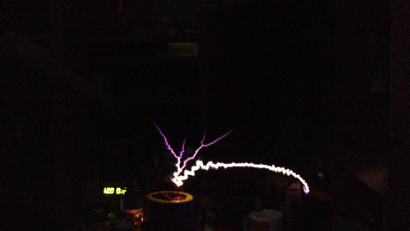
IMG_0457 221 by TwirlyWhirly555, on Flickr
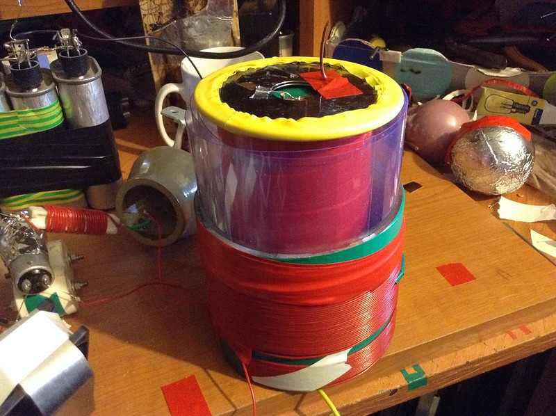
Sig , Like the super flammable secondary xD to stop arc overs there is 4mm of plastic laminate sheets round the secondary and 2 around the inside of the primary and above and tape , oh so much tape ...

IMG_0454 by TwirlyWhirly555, on Flickr
 
Last edited:


Back
Top