- Joined
- Dec 23, 2008
- Messages
- 3,948
- Points
- 63


Follow along with the video below to see how to install our site as a web app on your home screen.
Note: This feature may not be available in some browsers.


Hey, have you read the instructions posted on my site? I know they're a little out of date and I apologize, but you're welcome to ask me any questions directly about my stuff if you have questions otherwise.
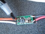
One thing that I noticed that probably has confused you about the Test Load is that the resistor placement is different than the instructions (should be on the pads marked R2) and I see that you have shorted the pads it should be on. I'm sure it was the assembly instructions that had you confused since the layout isn't exactly the same. The positive and negative pads on the board are connected to the driver output, you set your range to either RED or BLU, power your driver and measure voltage across the 1 ohm resistor.
I need to double check the instructions and the dummyload when I get home from work. Can you explain exactly what you mean by shorted?
RED as in red wavelength? Or does RED and BLU mean something else? RED is what I needed as the build uses a 5mW 625nm diode.
Next, for the driver, the bottom pads are simply for if you need somewhere to solder an extra pin for stability... they are not connected to anything. It looks like your positive pin is connected to the bottom, just connect it to the top (short the output pads before changing connections). The top pads are the ones you need to solder to (LD is + and GD is -). Their placement is standard configuration for most diodes (pin counterclockwise to case pin is positive, negative pin is either the case pin or the one clockwise to it), so you shouldn't have to twist anything to get it soldered.
Thank you, I understand now. I'll double check the instructions later but I read that as placing the pin at the bottom pad. thought the negative pin needed to be on the bottom. Had I known this soldering would have much easier using only the top pad and no worries of moving the pins. Embrassing question but what do you mean by short?
I'm going to desolder the driver and try again, and this time I can use the the test load as well.
Thanks everyone I'll have more questions when I get home.
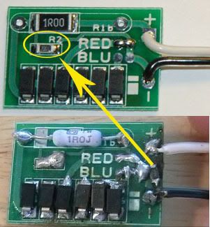
Checking the directions again now. That's why made that error with the resistor placement; the instructions were different. The resistor was not shown to be placed in the correct spot R2 as you indicated but instead the spot I had. Looks like I have to do some more soldering. That tiny resistor was extremely difficult for me to do as you can see by the mess, the spot was not easy. The proper spot will be much easier.One thing that I noticed that probably has confused you about the Test Load is that the resistor placement is different than the instructions (should be on the pads marked R2) and I see that you have shorted the pads it should be on. I'm sure it was the assembly instructions that had you confused since the layout isn't exactly the same. The positive and negative pads on the board are connected to the driver output, you set your range to either RED or BLU, power your driver and measure voltage across the 1 ohm resistor.
I've heard the term of course, not the same as grounding against static that's what I thought it meant. Shorting out electronics destroys them was my understanding so was unsure what you meant. That's what you meant by shorting out the pads it should be on. I'll read up on low resistance connections as I could write another thread on that term. wondering then so if a copper wire was connected from one battery to another that would be a a short? I'm trying to understand terms used, pardon my ignorance.Short is just a term for "low resistance electrical connection", ie touching two electrical points with something metal or connecting them with a wire, etc, which would "short it out". Typically I just use a pair of fine tipped tweezers or a flat head screwdriver to short the laser diode output contacts.
") I'm glad I had to do it myself and this way as I'm learning much more. I'm a bit afraid of soldering but I've just started and I never really did it before that's why my work looks so terrible. I had done a little practice but I still apply too much solder and SMD soldering is extremely difficult even with some tips I was given by electrofreak.
I'm glad I had to do it myself and this way as I'm learning much more. I'm a bit afraid of soldering but I've just started and I never really did it before that's why my work looks so terrible. I had done a little practice but I still apply too much solder and SMD soldering is extremely difficult even with some tips I was given by electrofreak.I read this part wrong on soldering the diode, I thought below meant below the LD on the board not next to. The rest of the instructions explain but that part was not clear. The diode pinout layout was the common one by the way.The positive (or LD) lead of the diode should be soldered to the pad below the ‘LD’ marking on the driver, while the ground (or GND) lead should be connect to the pad above the ‘GD’marking. The layout of this driver is the COMMON pin layout of MOST diodes, please verify
your pin-out with a reference source for your diode before connecting the leads
 I know what I'm doing. I have had no prior electronics training or formal education besides building PCs and that is nothing. I've had much more to learn. I think once I get over the learning curve so speak it will get easier. Now if I could figure out a good way to press the diode into the housing the axis module and I have read guides on it but still need to find something better to use.
")