Welcome to Laser Pointer Forums - discuss green laser pointers, blue laser pointers, and all types of lasers

LPF Donation via Stripe | LPF Donation - Other Methods

Links below open in new window

ArcticMyst Security by Avery

Setting diode on driver and dummy load

Joined
Feb 6, 2009
Messages
374
Points
0
I've been trying to find answers to my questions the past few days with no success.
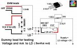
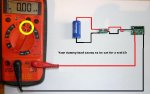
First of all how do I use a dummy load? I've managed to assemble the circuit but I have no idea where the power supply should be hooked up. I don't know how to simulate a test load. The information does not go into enough enough detail.

IMG%5D
wirhqa.jpg


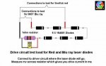
Next question, why can't I get the driver that I've set up to to receive any power output? The power supply won't supply it. My guess is what I did with the diode's pin here is the top.

111pcnn.jpg


Here is the bottom of the driver.

2v0mslf.jpg


This is the best picture I could get but I try to follow directions.The positive pin is soldered below the LD on the driver. The negative pin above the GD on the pad. Problem was I had to twist the pins to do this. The right pin broke off. That's my guess. As to what's wrong but I'm not sure. It be that the pin are not straight on he diode.With other builds I notice people have their diodes soldered to the driver completely straight.

It's a normal diode 5mW nm 635. I'm planning on putting it in a didla host this, is merely a test build for me. I feel like I'm very close yet missing something important. Any help would be appreciated! Pressing the diode is extremely tricky as well.
 
Last edited:


Joined
Mar 8, 2009
Messages
710
Points
0
People have a tendency to get too close to small objects when they try to take a picture. Stay farther away.
 
Joined
Oct 26, 2007
Messages
5,438
Points
83
Speaking of detail, we can't see anything in those photos. So it'll be hard to help you.
 
Joined
Feb 6, 2009
Messages
374
Points
0
:p I have an old camera too, that's 90% of the problem. Ignoring the lousy photos (I tried I, really tried to get better ones but the camera is a 5.0 megapixel 5 years old).Figuring this out has has been difficult with no background in electronics outside of PCs. The camera was meant to show I had twisted the diode pins but only I can tell it seems. That dummyload should be thumbnail picture that can be clicked on.

Without pictures I have the same questions. How do I set up a dummy load? Where do I attach the power supply connectors? Pictures aren't needed to make that concept clear. The dummy load functions as false driver as I understand but my multimeter isn't picking anything up with it connected. I realize this are extremely basic questions but I've never done this type of work before.

As for the driver my question could have simply been do all the pins need to be straight on the diode or can I twist them to fit on the driver? That's what I did because naturally the negative and positive pins were in the wrong position and needed move further. The 3rd pin (used for nothing) ended up coming off.

I will desolder and retry with my other diodes but knowing how to set a dummyload and where the diode should properly be soldered would be huge help.

Sorry about the lousy pictures!

thanks,
 
Last edited:
Joined
Apr 29, 2009
Messages
49
Points
0
For a dummy load you can buy a 1 Ohm resistor from radio shack for a few cents and attach one end to the positive end of the diode feed and another to the negative end. Get a voltmeter and set it to millivolts and place one end on each side of the resistor. Your reading should be the output current. Hope that helps :)
 
Joined
Jul 24, 2007
Messages
2,749
Points
0
I know the first picture is of a DDL circuit but the test load goes in the same place whatever circuit you use. The picture of the test load has red (+) and black (-) wires, these go to the pads where the ld +- are marked on the circuit board, the power supply goes + to the white lead - to the black lead.

Have a look on your camera to see if there is a setting that brings up a little flower on the viewing screen, this is macro.... you can then get closer to the subject of the photo, half press the shoot button and check that the image is clear on the screen, if so push the button all the way to get the photo taken.

Regards rog8811
 

Attachments

  • DDL circuit test01.jpg
    DDL circuit test01.jpg
    46.9 KB · Views: 3,302
  • test load01.jpg
    test load01.jpg
    41.2 KB · Views: 2,286
Last edited:
Joined
Dec 23, 2008
Messages
3,948
Points
63
I use the way rog is showing. It is very easy. umm about where set up power. you attach the dummy load to your driver in the spot where your LD would go. then use the diagram rog posted. hope that helps

michael
 
Joined
Apr 29, 2009
Messages
49
Points
0
Why do you need the 6 diodes? I know what they do but wouldn't one be able to do it?
 
Joined
Jul 24, 2007
Messages
2,749
Points
0
They each drop .7v, multiply that by six = 4.2v which is pretty close to the voltage drop across an 803T LD so you are matching the load that the driver sees.

Regards rog8811
 
Joined
Feb 6, 2009
Messages
374
Points
0
I know the first picture is of a DDL circuit but the test load goes in the same place whatever circuit you use. The picture of the test load has red (+) and black (-) wires, these go to the pads where the ld +- are marked on the circuit board, the power supply goes + to the white lead - to the black lead.

Have a look on your camera to see if there is a setting that brings up a little flower on the viewing screen, this is macro.... you can then get closer to the subject of the photo, half press the shoot button and check that the image is clear on the screen, if so push the button all the way to get the photo taken.

Regards rog8811

Check my first post in this thread again Rog.;) I found that I could take snapshots with my camcorder and now much better better pics have replaced the old ones. See if that helps, I'm still reading the thread but I'm curious why my diode setting did not work. Now everyone should be able to tell me easily with clear pictures.

Thanks,

I use the way rog is showing. It is very easy. umm about where set up power. you attach the dummy load to your driver in the spot where your LD would go. then use the diagram rog posted. hope that helps

michael

:slapshead: I knew that's what I was missing! No wonder the test load was not working! That covers that problem. Now just wondering what my error was with the diode.

Yes, my soldering work is terrible. I've barely just started so a little mercy on that part.
 
Last edited:
Joined
Dec 23, 2008
Messages
3,948
Points
63
Maybe I am reading wrong but I do not really see a question pertaining to LD problems. BUT.... from my experience the LD pins should be soldered on the same side of the driver board.

michael
 
Joined
Jul 24, 2007
Messages
2,749
Points
0
from my experience the LD pins should be soldered on the same side of the driver board.
Agreed.....they should be same side
Jees, I am loosing it, just realised first picture is the dummy load......Black wire to LD- white wire to LD+
Regards rog8811
 
Last edited:
Joined
Feb 6, 2009
Messages
374
Points
0
I followed the directions given and that's what happened. The positive pin need to be below the LD and the negative above the GD. Yet got nothing when I hooked it up. I connected it straight to the power supply but no power would go out. Right to those plus and - holes on the driver. I believe I had wire set there as well.

is there an example of competed driver with the diode attached tha I can look at? My own lasers have a large amount of expoy so I can't use my own material.
 
Joined
Jul 24, 2007
Messages
2,749
Points
0
I should have reviewed this before posting it may not show what we want......but both connections on top

Regards rog8811
 

Attachments

  • Link dummy01.jpg
    Link dummy01.jpg
    40.2 KB · Views: 2,212


Top