Welcome to Laser Pointer Forums - discuss green laser pointers, blue laser pointers, and all types of lasers

Buy Site Supporter Role (remove some ads) | LPF Donations

Links below open in new window

ArcticMyst Security by Avery | Browser Hide by Avery

Raman-spectroscopy

That looks very nice. Ok so I did calibrate two units tonight. Used like 6 laser, hg lamp, hydrogen lamp, multi line hene....about 25 lines for each. I had to remove the yellow filter in the slit to extend the range. Goes well into the UK. One unit goes at least to 350 and the other beyond 600 but I didn’t have or sourve to use to go farther. Best I could do is 640 and 405 because of available line sources. Anyway yes just move the grating. Be careful of second order issues.


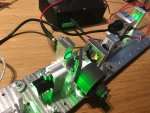
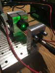
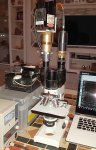
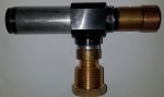
Here now as desired and promised the description of the featured longpass-filter-holder with collimator and SMA905 connection.
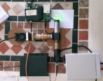
Essentially, I designed and built this part to connect a spectroscope to a microscope.
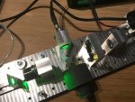
Of course, this structure is only an example, as each of you has different components available.

As a base I needed a housing, since the filter has a diameter of 25 mm, I took this of a 1.25 inch eyepiece, which can be disassembled as far as possible.
Mine belonged to a russian stereoscopic light microscope MBS-10, from time to time you can find such a one on ebay, like e.g. here:

link:

https://www.ebay.de/itm/14x-Okular-...424887?hash=item285b2ddfb7:g:D4cAAOSwJRZaZeyF

2So2xPz.jpg


There are 4 grub screws on the upper lens holder.

zztLsuq.jpg


This can be removed for easier integration of parts.

O8uLrDW.jpg


Inside the upper lens frame sits a ring nut.

UPpkZHG.jpg


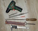
Since I have no such tool, I have this ring nut turned out with a scissors.

tnuEwGk.jpg


Of these three parts I only need the black top lens holder.

Cqn8ifz.jpg


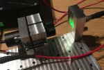
From the known beam splitter, I have taken the SMA905 collimator after loosening the small grub screw.

Hc7tuOr.jpg


The SMA905 collinator should now be insalled in this lens frame.

JiGKLtR.jpg


I have drilled these on both sides with a countersink until the thread of the SMA905 collominator can be screwed in.

vU5bl7O.jpg


I then screwed in the SMA905 collominator only provisionally. Since I have no fine thread nut, it was only at the shot, after the total assembly (if everything fits) it was fixed with adhesive.

Pvo0nnW.jpg


Now the eyepiece cylinder is disassembled, also here I unscrewed the lock nut with a scissors from below.

Nz937JH.jpg


The entire lens package is dumped, only the glass lenses are no longer needed, the rest is in use.

2ZJ505f.jpg


I especially used these two aluminum rings. In the cylindrical the 25 mm long pass filter fits exactly into it and thus serves as a spacer ring to the cylinder.

sAxlIDt.jpg


Instead of the stack of lentils, I have now put together different items. Lock nut, rubber seal as damping and distance, filter in the spacer ring just mentioned, seal, 2nd distance ring with seal.

JMHRdWD.jpg


LFhdemZ.jpg


This construction is not high enough as a stack, because the internal thread for the locknut does not stick out far enough.
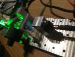
So I put on top a 20 mm pipe-extension with matching diameter.

S61FHvK.jpg


I had previously drilled this tube extension to fit inside as a guide, so that the lens sleeve of the SMA905 collominator fits into it.

YNZk2mD.jpg


After all, hopefully everything fits, the upper lens holder is screwed back firmly and NOW the SMA905 collominator fixed with adhesive from above.

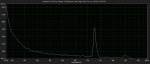
DONE and working ...

CXjeh5V.jpg


aJF5b2d.jpg
 
Very nice, comprehensive review of how you incorporated the eye piece into your beam splitter, chloderic. I see from your design that I may not be able to follow it completely, but it does give me a place to start working from. :thanks:
 
Thank you. What size is that grub screw. Can't seem to find the right size. Everything I have is too big.

Ok so if I illuminate an object with a laser and use this device to collect signal will I see a spectrum? So the longpass is for stokes like and you use a highpass for antistokes I guess.

I thinking to just bolt the laser on this assembly with a little mirror to direct the beam on the object just below this lens collector. Maybe add a focusing lens too for the laser anda little mount to hold it all wit ha table at the laser focus.

I was able to move the grating and get down to the ir range. This detector is really sensitive in the blue oncde you remove the sma input filter. Takes minutes to change it and hour or so to run the cal lines. Still ordering usb2000/4000. Tired of messing with them and just want them to work.

So I setup a unit as it came to me with the sma filter removed and the baffles removed. I don't see any raman lines just a little bleed through from the laser. Guress wha the was from...DUST! the laser light reflected off the dust and was stroner than the raman signals. Tried a dark field to remove the signal but still there. I tried a lump of coal, paper, wood, my hand, plastic. I see nothing.

Last, is the window on the front of the stock raman unit a filter too? Will have to spec it once I get it out of the housing.
 
You might have to get the OEM software from Ocean Optics for your new spectrometer. I couldn't run mine on the Science Surplus one. But, I like the OEM software much better.
 
I plan to buy the full suite with the matching libraries. I'm talking with the reseller in Florida tomorrow. Think I found a 200-1100 model with 1nm resolution. That will do fine. These bw models are nice toys but I want to use rather than tweak the thing.
 
I know that guy in Florida as I had spoken with him several times while looking for my Ocean Optics spectrometer. I don't think he can help you with the software as I recall his suggestion was to use Ocean Optic's 10 day trial and keep resetting the date on your computer so it never expires. That is nonsense as you can't do this in practice, so you will end up purchasing the software. He is likely able to do this because he sells spectrometers for a living and each one is different. You, however, won't be able to do this as you will only have one spectrometer.
 
Last edited:
Here is an interim report on the already presented device nr 3 of 4, which i called "probe".

After another modification, a raman-shift can now be tickled out.
But the laser power is still too much scattered within the angle tube adapter, so I have to open the whole part again to see what's going on.

Basically you can see, however, that hereby a raman-shift is visible.

In the speckrum, this shift is at 10000000 / ((10000000 / 532nm) - (1332cm-1)) = 572.57nm, see picture 3.
 

Attachments

  • 1.jpg
    1.jpg
    216.5 KB · Views: 33
  • 2.jpg
    2.jpg
    360 KB · Views: 35
  • 3.jpg
    3.jpg
    147.7 KB · Views: 42
A collection of nice posts in this thread !!! Interesting !

I have also cobbled together a raman setup with parts from the BW tec beam splitters, the optical fibers and a part from one of the 473 laser heads, in combination with some home-made parts (I am the lucky owner of a mill, lathe and home-built cnc-mill) and some ebay filters/dichroic mirror (seller: bjomejag). An overview of the setup:
attachment.php

Bottom left is the sample position in front of the front lens of the BWTech beam splitter. A dichroic filter (540 DRLP) under 45 degrees acts as the beamsplitter. The black cylinder is a home-build beam stop. At the top left/centre is the laser input from the fiber with the lens assembly from the beamsplitter (the one chloderic is using in his setup). Behind the beamsplitter is filter holder which currently carries 540AELP and 538 AELP long pass filters. It was initially not the intention to use the dichroic and both long pass filters, but they do a great job in getting rid of almost all 532 nm laser light. Behind the filter is again one of these lenses from the beamsplitter to couple the output through a fiber to the spectrometer.

The setup seen from above:
attachment.php


Actually, this setup is pretty close to the setup of the BW Tech beam splitter, but with a dichro-mirror for 532nm and with the long pass filters included. As a laser, I currently use an ebay 150 mW laser (no single mode) mounted in a self-made pan-tilt holder (steel ball in one corner, 2 screws in 2 other corners and o-rings acting as springs to keep everything together... works great !):
attachment.php

With the pan-tilt, the laser is aimed into a fiber-coupling taken from one of the 473nm BW Tech laser.
attachment.php

With 4 screws, the tilt of the fiber coupler can be changed slightly (a small O-ring behind the coupling gives a bit of flexibility).

The following spectrum was obtained with this setup (confirming that the diamond in the wedding ring I gave to my wife was not fake :shhh:):
attachment.php

Note that the 532nm line is completely gone in this spectrum ! The bump in the background seems to be coming from the fact that the system was picking up light from the computer screen when acquiring the background signal. I should put everything in an enclosure.

I still do have some issues with the setup, which I do not fully understand: for instance the 3 strong peaks around 540nm in the following spectrum seem to be always present (but with strongly varying intensities) for samples which strongly reflect the laser back into the setup. I do not understand where the frequency shift comes from (I don't think it is straylight in the spectrometer since I would expect the 532nm line to be the strongest in that case). Anyone any idea ?
attachment.php

By the way, the spectrum is from the top side of an Apple magic mouse.
 

Attachments

  • IMG_1059_scaled.JPG
    IMG_1059_scaled.JPG
    137.9 KB · Views: 124
  • IMG_1060_scaled.JPG
    IMG_1060_scaled.JPG
    132.5 KB · Views: 116
  • IMG_1061_scaled.JPG
    IMG_1061_scaled.JPG
    108.6 KB · Views: 116
  • IMG_1063_scaled.JPG
    IMG_1063_scaled.JPG
    128.5 KB · Views: 19
  • Screen Shot 2018-06-04 at 22.37.51.png
    Screen Shot 2018-06-04 at 22.37.51.png
    26.8 KB · Views: 117
  • Screen Shot 2018-06-04 at 22.36.46.png
    Screen Shot 2018-06-04 at 22.36.46.png
    29.7 KB · Views: 117
  • IMG_1062_scaled.JPG
    IMG_1062_scaled.JPG
    112.4 KB · Views: 114
...in combination with some home-made parts (I am the lucky owner of a mill, lathe and home-built cnc-mill)

....At the top left/centre is the laser input from the fiber ......

.... I still do have some issues with the setup, which I do not fully understand: for instance the 3 strong peaks around 540nm in the following spectrum seem to be always present (but with strongly varying intensities) for samples which strongly reflect the laser back into the setup. I do not understand where the frequency shift comes from (I don't think it is straylight in the spectrometer since I would expect the 532nm line to be the strongest in that case). Anyone any idea ?

Me again, very impressiv :worthy: :gj: !!!

I have some ideas...

But first of all, well, because with your equipment , I can only almost keep up.
My "mill, lathe and home-built cnc-mill" see picture in the attachment ... :whistle:

Here with this effect, I would say from the pictures that you have the fiber optics with the 200 mW drastically overloaded and now see the RAMAN effect of the fiber-optic itself.
Try with a provisional construction without the fiber optic direct after the laser , because such an effect I have seen in such a case before.
Therefor i use no fiber with such an power, i will not buy any fiber wich will fit for it.

Question from me , why have you used the red fiber instead of the orange one at the spectrometer, it has a bigger diameter ... yes ... is it better in this case ?
 

Attachments

  • 1.jpg
    1.jpg
    377.7 KB · Views: 19
My "mill, lathe and home-built cnc-mill" see picture in the attachment ... :whistle:

That's how I started as well ! It is amazing that with a few tools, a bit (sometimes a lot) of time and effort, you can make new tools which make it much more easy to make yet more/better tools,... and before you know, you do not have enough space in the house/shed :crackup:


Here with this effect, I would say from the pictures that you have the fiber optics with the 200 mW drastically overloaded and now see the RAMAN effect of the fiber-optic itself.
Try with a provisional construction without the fiber optic direct after the laser , because such an effect I have seen in such a case before.
Therefor i use no fiber with such an power, i will not buy any fiber which will fit for it.

Interesting thought. I'll check that one out when I have a bit of time. At one point I did clearly see a contribution from the fiber in the output... there was even light leaking from the sleeve, but this was when by accident, I did not respect the minimum bending radius.

Question from me , why have you used the red fiber instead of the orange one at the spectrometer, it has a bigger diameter ... yes ... is it better in this case ?

I have to admit that until now, I did not realize there was any other difference between the red and the orange fiber than the color of the sleeve. Looking at the fibers themselves now, I do see the difference in diameter of the actual fiber (in my case, orange are the thicker ones). I'll check if it makes any difference, using the orange one for the coupling with the spectrometer, hoping to capture more signal.

Thanks for the suggestions ! :beer:
 
Last edited:
Hello chloderic,

Your comments made me curious and I powered up the setup to do some test. Surprisingly, I did not manage to reproduce the high peaks around 548nm today. Since I took the previous spectra, I did remove and place back the dichroic mirror, hence its exact position and alignment might have changed. But this makes me believe that these peaks were not coming from the raman signal from the fiber itself (thinking further about it, I did notice last time a big variation in those peak intensities when only moving the sample, which is why I believe the peaks originated somewhere in the detection path and not in the laser input optical path).

The background "bump" is still present in all spectra, also when taking care to avoid any other light input into the input to the spectroscope. Fluorescence in the fibers ?

I did replace the red fiber towards the spectrometer by the orange and there is a clear difference, as can be seen from the following spectra (obtained from a 3D printed object printed with transparant PETG filament):

attachment.php

Obtained with the red optical fiber

attachment.php

Obtained with the orange optical fiber.

The signal is clearly stronger when using the orange fiber ! It seems better to use the orange fiber, at least in the output optical path! But also notice the difference in the shape of the background signal!

In general, I conclude from all this, that it is important to be very careful with interpretation of the results obtained with this setup... it is very easy to have artifacts in the spectra. Furthermore, it is clear that I do not have yet a good feeling/understanding about which alignments result in which changes in the spectra... there are probably still quite some optimisation/improvements possible.


PS Related to my previous post about manufacturing capabilities: having these tools at hand makes it easy to produce good-looking and accurate setups, but they are absolutely not mandatory to have in order to make a working setup with these BW TEC elements. Your setup with the microscope is very impressive ! And with a drill, some L-brackets and a bit of creativity a similar setup as mine, or another possibly better setup can be easily built !
 

Attachments

  • Screen Shot 2018-06-05 at 22.46.21.png
    Screen Shot 2018-06-05 at 22.46.21.png
    30.2 KB · Views: 102
  • Screen Shot 2018-06-05 at 22.45.38.png
    Screen Shot 2018-06-05 at 22.45.38.png
    29.9 KB · Views: 101
Can you do a "dark scan" with the fibers actively exposed. This would subtract the effect of the fibers.

I have an ocean optics HR2000 200-1100nm unit coming along with Hg/Ar source. This should step up my game a lot. I have a 538nm edge filter coming too and a 532 line filter. Has anyone tried to tec control the dpss to lock the 532 signal? So far I'm not seeing much I actual believe is raman even using the bw Tek setup and 473.2nm laser. Kind of want to get that working before moving to 532 and ultimately 785nm.

PS: Cheap cal sources https://www.carolina.com/physical-science-light-and-optics/safe-spectrum-tubes/FAM_755582.pr

https://www.effemm2.de/spectragryph/down_dfg9us90e578z.html free software
 
Last edited:
Hi, the last great device from diber of course ... I could not sit on me like that :evil:

So I wanted to introduce my next prototype # 5 of 5.

Here I have successfully put together with result.

- cheap Bresser Biolam transmitted light microscope
- dpss laser 532 nm set to about 300mW (from a total of about 930mW)
- a used additional binolular tube from ebay for 25 €
- a few pipe fittings and a tubus clamp
- the known collimator filter adapter
- BW-Tek spectrometer

Result relatively strong ramansignal 1332 cm-1, as expected ....

diber ..... it is your turn ....:D
 

Attachments

  • 1.jpg
    1.jpg
    224.6 KB · Views: 41
  • 2.jpg
    2.jpg
    157.3 KB · Views: 44


Back
Top