Welcome to Laser Pointer Forums - discuss green laser pointers, blue laser pointers, and all types of lasers

Buy Site Supporter Role (remove some ads) | LPF Donations

Links below open in new window

ArcticMyst Security by Avery | Browser Hide by Avery

Raman-spectroscopy

Ah. Okay. I see what you mean now. I did see the 532nm DPSS laser in your photo. I have several that are the same or larger. I think this might be a good wavelength for me to use as I would be interested in mineralogy analysis.


I found a nice diagram of one over at B&W Tech's website.
Components of a Raman Spectrometer - B&W Tek
R-F-06.jpg


After looking at this image some more, it makes me wonder if the two fiber optic cables are the same size or different. In the case of these machines and if they are different sizes, it would seem like we need to keep up with which one was the excitation fiber optic and which one was the other. Does anyone know?
Yes, this is such a device, you can find it in different constructions. And for the fibers, the 2 which comes with the device we are discussing about " B&W-tech Spectrometer & 473 module: Setup+Mods+Info*", the orange one is for the spectrometer and the red one for the laser ....
 
Yes, this is such a device, you can find it in different constructions. And for the fibers, the 2 which comes with the device we are discussing about " B&W-tech Spectrometer & 473 module: Setup+Mods+Info*", the orange one is for the spectrometer and the red one for the laser ....

I'm glad I asked... thanks for clarifying.
 
Here I found a very innovative RAMAN-Fliter .... it's worth it to read it!

"Raman Microscope Laser Reflector

Designed for use in an epi-illumination geometry Raman microscope, the laser reflector is an image quality AR-coated glass element with a centered 2mm diameter aluminum mirror. Mounted at 45°, it reflects the laser into the objective, and then transmits all but a small fraction of the Rayleigh and Raman scattered light collected with the objective. For example, using a 40X objective having a numerical aperture of 0.8 and a focal length of 4mm, only 3% of the Raman signal is lost upon transmission through the laser reflector. This loss is related only to the size of the mirror and the collection properties of the microscope objective. Used with an ALPHA-Epsilon edge filter for Rayleigh rejection, this allows the measurement of Raman lines very close to the laser wavelength with little loss in signal throughput."

The whole text you will find here:

Link: Raman Spectroscopy | Omega Optical
 

Attachments

  • raman_micro.jpg
    raman_micro.jpg
    6.7 KB · Views: 40
Yes that is closer to what I want. So I got one of those ebay units. I can't seem to make anything shift the way it is setup even with baffles out. Has anyone got the stock 473 raman running?
 
Yes that is closer to what I want. So I got one of those ebay units. I can't seem to make anything shift the way it is setup even with baffles out. Has anyone got the stock 473 raman running?

Yes , i posted one spec at the other page .
Please post your assembly to undertstand what you did.
 
Last edited:
I can't seem to make anything shift the way it is setup even with baffles out.

Again to this part , i would like to have a look in the spectrum form you, maybe you can post such one here?
Rename it to *.txt and you can attach it here .
 
Has anyone successfully realigned one of these after changing the grating position? I haven't gone further than calibrating one that seems to work fine between 460nm and 650nm. I haven't found the time, or the need, to change the grating position on one yet.
 
I moved the grating and get spectra well out in the 800-900 range. Could not go the other way. You don’t even see 405 after the slit. Something blinks the higher no range. Can’t say it’s the detector as the beam never makes it there. Surplus science does it but they change gratings and detectors. Not worth it really. If you are going do that but a usb2000.

Now calibrate well I’m having issues. The intercept is negative. I’m getting a better source of lines this weekend. I used neon. The spectra looks right but the scale is not and 532 is right. So does 473. I had 473, 532, 540, all the neon lines down to 750. So theoretically 473-750 which is too wide. My idea is the wavelength gets compacted on the detector the fatter you turn it so while it looks wider, the resolution is not as good.
 
It shouldn't get wider as that is a function of the grating in use. You likely have a severe misalignment of the bench now. Try putting the grating back in its original position and see if your alignment problem is resolved.
 
Here I would like to introduce the next prototype number 4 with RAMAN shift.

used parts:
- binocular tube (modified)
- microscope-lens
- dpss laser 532nm
- laboratory power supply for controlling the laser power (here about 200 mW)
- long pass filter assembly as already posted
- microscope tube connectors and pipe fittings
- B & W-TeK spectrometer
- fiber optics
- spectrum studio
- libreoffice postprocessing sheet
- crystal sleuth software

Images:

- binoculartube
- assembled prototype 4
- spectrum 1; left laser , right shift of diamond
- spectrum 2, zoomed
- result of crystal-sleuth

the whole assenbly is not perfect yet, but just with simple cheap parts built and expandable.
 

Attachments

  • binocular.jpg
    binocular.jpg
    220.9 KB · Views: 42
  • device 4.jpg
    device 4.jpg
    343.8 KB · Views: 48
  • diamond1.jpg
    diamond1.jpg
    160.2 KB · Views: 46
  • diamond2.jpg
    diamond2.jpg
    160.6 KB · Views: 45
  • CrystalSleuth diamond.JPG
    CrystalSleuth diamond.JPG
    151.3 KB · Views: 45
I like it, chloderic. I may just follow what you have done here for my project. I'll have to wait on it though. Seems I have some new and unexpected expenses now.
 
Here are just a few pictures from the current hardware project.
You surely know the part, which one finds, if one enters in a picture search RAMAN PROBE. This is probably the simplest version you need in addition to a spectrometer and a laser.

Let's see what the assembly of garage parts is good for, when he's done.
The central part is camera-adapter with an splittercube inside.

Maybe i can put some candles in when it is chrismas ... ?

Cloderic,

many thanks for the boos you are giving to this thread.
Please, can you tell me more about how you coupled the optical fiber SMA to the eyepiece?
Is there some distances you have to respect to optimase the signal collection?
Can you do a sketch to explan how you adjust the distances and different parts to conenct the optical fiber to the eyepiece.
Thank you again

C

Hello Civitus,
I understand your critical question about the optical composition which implies the very important compliance of different focal lengths and so on.
In this case, I solved the problem fairly easily and reliably with a few compromises.
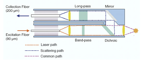
I try to describe the beam path only theoretically:

From the laser, a parallel beam path (with divergence neglected by me) passes unchanged through several prism through the objektiv-lens.
There is the object to be examined in the focal point.
The raman signals now goes from this focal point through the same lens and generate behind this in turn a parallel beam.
Once again, several prisms allow this bundle to pass vertically through the filter onto the collimator,
at the focal point of which the entrance surface of the fiber optic is defined.

If one therefore pays attention that the object to be examined lies at the focal point of the objective,
the length structure of the entire unit is irrelevant, because the light bundles running within the unit are parallel to one another.

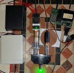
With such a construction of course, an xy-table in the focal point of the "object" makes sense, so you can adjust quite precisely the maximum.
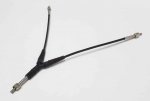
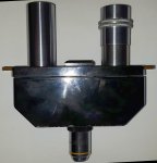
My pictures showed only one experimental setup, so another prototype.

Because of the sma connection part, I am still a documentation guilty, to do this I have to disassemble the part again, which had prevented me yet from this......
but will follow sometime ......


Back
Top