Welcome to Laser Pointer Forums - discuss green laser pointers, blue laser pointers, and all types of lasers

LPF Donation via Stripe | LPF Donation - Other Methods

Links below open in new window

ArcticMyst Security by Avery

Raman-spectroscopy

Joined
Mar 1, 2017
Messages
81
Points
8
Thank you, thank you, thank you! This is exactly what I got these for and I'm looking forward to following this thread.


Is there another reason besides fluorescence for using a 532nm laser instead of the 473nm laser?

Yes,
in fact, each laser excitation is better addapted to some materials.
the Raman response of molecules is different from an excitation to an other. You should first know what kind of mecules or material you intend to analyse.

C


Joined
Sep 26, 2016
Messages
52
Points
8
Yes,
in fact, each laser excitation is better addapted to some materials.
the Raman response of molecules is different from an excitation to an other. You should first know what kind of mecules or material you intend to analyse.

C

Thanks, for starters anything that can be done with the 473nm laser. I've been googling to try and find out what works good for this wavelength. I'm still so new at this that I just want to play with what I have and learn from it.

I play around with making graphene and one day I would like to work my way up to being able to sample that.
 
Joined
Mar 1, 2017
Messages
81
Points
8
If i understand this here, you can see such an assembly in the picture of my functioning device at page 1 . The 2 beams in and out will run 2 separate ways. I have attached a picture of the beampath of my device #1. The blue path is the laser and the red path ist the backscattering. That meens i have attached a 532nm laser left at the binoculartube , the filterassambly (i posted it) at the middle with connected spectro at the sma.
Additionally there is a 5 M-pix camera installed at the right to adjust the position in the target. AND ... it is working.

Source-webside of the picture : MBS-10

Dear Choledric,
Your system is smart and elegant, but, I think that it will not be efficient, inthe sens you are loosing lot of Raman signal, may be you are just collecting 25% of the total signal that you can.
In fact, the objective collects the Raman signal, but haf goes to the right and the other half goes to the left, here you have 50% losse
then, half of the signal goes to the eyepiece-SMA and half goes to the camera.

I frankly think that you can increase the Raman signal by a factor of 4!
but, still bright idea for strong Raman emitting materials.

please, can you advise and share how you converted your eyepice to to an SMA-connector?

thanks a lot
C
 
Joined
Mar 1, 2017
Messages
81
Points
8
Thanks, for starters anything that can be done with the 473nm laser. I've been googling to try and find out what works good for this wavelength. I'm still so new at this that I just want to play with what I have and learn from it.

I play around with making graphene and one day I would like to work my way up to being able to sample that.

No problem, we are here to share our experiences.
For graphene, go with 532nm wih no problem, I have good experience with carbone nanoparticles with 532nm

C
 
Joined
Sep 26, 2016
Messages
52
Points
8
No problem, we are here to share our experiences.
For graphene, go with 532nm wih no problem, I have good experience with carbone nanoparticles with 532nm

C

Thanks, that helps a lot. I'll keep an eye out for some good deals on a 532nm lab laser and beam splitter cube. In the meantime, the quest is on for some good samples that will work with 473nm :)

So far I've seen diamond and acetone sampled here and I'm guessing that other liquids solvents may work too.

I do a bit of essential oil distillation as well and I wonder how well it would do at checking how pure the distillations are :)
 
Joined
Jan 21, 2018
Messages
324
Points
43
Dear Choledric,
Your system is smart and elegant, but, I think that it will not be efficient, inthe sens you are loosing lot of Raman signal, may be you are just collecting 25% of the total signal that you can.
In fact, the objective collects the Raman signal, but haf goes to the right and the other half goes to the left, here you have 50% losse
then, half of the signal goes to the eyepiece-SMA and half goes to the camera.

I frankly think that you can increase the Raman signal by a factor of 4!
but, still bright idea for strong Raman emitting materials.

please, can you advise and share how you converted your eyepice to to an SMA-connector?

thanks a lot
C

Hello Civitus,

I would like to discuss with you here, because that's the most effective way to experience and exchange ideas.
That's just the basis of communication.
For this reason, I sometimes put here one or the other facet something irritating.

In this sense I would like to contradict you in a few points:

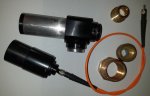
- As already described above, I swap out the two beamsplitter at the recording of the spectacle from the beam path.
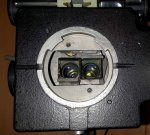
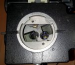
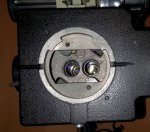
For this purpose a lever on the left side of this assembly moves the two beam splitters. To illustrate it I took up the tube head.

In picture 1 you can see the two beamsplitter swung in, the picture 2 then partially swung out , and in picture 3 these are completely swung to the side and no longer in the beam path.
The intermediate objective revolver (referred to in the sketch as the galilei system) can be brought to a throughput position and in this position no additional lenses or other optics are in the beam path.
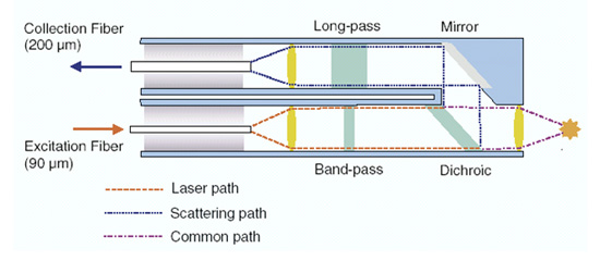
The first 50% loss described by you are then already no longer available, because the laser goes directly to the sample without any obstacle and the ramansignale directly back through the lens through the langpassfilter in the colimator.
This then collects the light at the focal point on the input of the fiber optic.
In others systems you have to find a way to coupli in the laser beam in the optical path, here it is no so and i spare some losts, because no such part (like a dicro, mirror or cube) is in the path.

- Since the raman signals have a random emission direction, the small convergence angle of 13 ° is not particularly relevant, as long as the structures on the sample surface do not shadow, in the 90 ° solution that may be a problem.
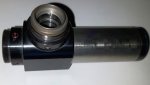
In a 0 ° system, the signal goes so synonymous through the lens, but my lens is much larger in diameter (48mm!) and thus considerably brighter.
Certainly, the just described convergence angle and the large working distance is a disadvantage,
but with this system I have to compromise, because I want to be able to cool the objects under investigation in a chamber with a quartz window and the minerals to be examined can have a certain size and do not fit under a normal microscope.

I know this system is not optimal, but it's just one of several solutions I share and is is built with parts i have.
Over the next few weeks I will introduce the two other assemblies that have other advantages and disadvantages.

First there will come the from you desired detail-description of the sma connection, this is a bit of work, so please be patient with me.

Then I am looking forward to fruitful discussions and exchange of opinions.
 

Attachments

  • 1.jpg
    1.jpg
    374.3 KB · Views: 33
  • 2.jpg
    2.jpg
    375.7 KB · Views: 29
  • 3.jpg
    3.jpg
    358.9 KB · Views: 28
Joined
Jan 21, 2018
Messages
324
Points
43
So looking for filters. How narrow do I need to make the filters? For example I see a 520nm band pass filter for the 520nm laser diodes but the filter is about 50nm wide. They say 15nm but the graph looks more like 50nm to me. I could heat tune the laser diode so it falls at say 525nm and cut off one side. Not sure how wide band the diodes are. The dpss yellow is 6nm wide my so called 532 is really 534nm. Looks like you need to really control the laser line to make this clean up work. I’m not convinced the 473 lasers are always 473 yet either. Hence...maybe not cleanup the laser and use a better low pass/longpass filter. Seems you can get much sharper edges for those. Issue at 532 is your right in the middle of the spectrum so you must use a band pass and if it’s wide you lose spectrum. Thinking of both stokes and anti at the same time. Speaking of which which is best....so many questions. Absorption is much easier with specs than this.

Last has anyone hooked this up to a spec library yet?

Here a integrated database of Raman spectra, X-ray diffraction and chemistry data for minerals that i am using, there is also the needed software for this to download ... it is FREE !!! I convert the csv output of the spectrum-studio with excel to use it herewith.

LINK: Database of Raman spectroscopy, X-ray diffraction and chemistry of minerals
 
Last edited:

kecked

0
Joined
Jun 18, 2012
Messages
950
Points
63
That’s great! Do you know of one for basic chemicals, organic, toxins...
 
Joined
Sep 20, 2013
Messages
17,414
Points
113
All my past experience with Raman spectroscopy has come from Ocean Optics which makes these systems as ready to use turn key operations. Not having immediate use for this, I didn't research it much, but knew the various items needed to accomplish it were available through Ocean Optics. I have found all this quite informative, especially when I searched for more information on the subject. Thank you for this window into an analytical spectroscopy I had only a passing knowledge of before now.
 
Joined
Jan 21, 2018
Messages
324
Points
43
That’s great! Do you know of one for basic chemicals, organic, toxins...

If you have a tyical spectrum of such a chemical, you are able to transform it to that format too and integrate it to this database.
 
Joined
Jan 21, 2018
Messages
324
Points
43
Here are just a few pictures from the current hardware project.
You surely know the part, which one finds, if one enters in a picture search RAMAN PROBE. This is probably the simplest version you need in addition to a spectrometer and a laser.

Let's see what the assembly of garage parts is good for, when he's done.
The central part is camera-adapter with an splittercube inside.

Maybe i can put some candles in when it is chrismas ... ?
 

Attachments

  • 20180525_195559.jpg
    20180525_195559.jpg
    197.5 KB · Views: 38
  • 20180525_214546.jpg
    20180525_214546.jpg
    235 KB · Views: 43
  • 20180525_230216.jpg
    20180525_230216.jpg
    400.5 KB · Views: 46
Joined
Sep 20, 2013
Messages
17,414
Points
113
I like it. I see pipe parts and stuff from all parts of a hardware store. I'm still a little confused how you have optically connected the laser to the sample being examined, but I'm sure all will be revealed in time.
 
Joined
Jan 21, 2018
Messages
324
Points
43
I like it. I see pipe parts and stuff from all parts of a hardware store. I'm still a little confused how you have optically connected the laser to the sample being examined, but I'm sure all will be revealed in time.

Because the most of my optical parts are dimensioned in inch the usage of pipe-parts is easy. You only have to measue them out to find one which will fit or buy a used or new one for a dollar. The object will be at the left side of the 3-th picture ... a raman-probe is to be used in a case of big objects that will not fit under any device. Maye you would goole with the words " raman probe" to see examples.
The detailed construction of this device i am building now will be posted later.

PS: you can see an dpss laser in the last picture .... have a look
 
Last edited:
Joined
Sep 20, 2013
Messages
17,414
Points
113
Are you talking about a cuvette? That was what I thought of when you mentioned this.
 
Joined
Sep 26, 2016
Messages
52
Points
8
no.... such a tool:

Raman Sampling Tools | w2innovations.com

there are many different part like that ....

In this case a "PROBE" is a device

I found a nice diagram of one over at B&W Tech's website.
Components of a Raman Spectrometer - B&W Tek
R-F-06.jpg


After looking at this image some more, it makes me wonder if the two fiber optic cables are the same size or different. In the case of these machines and if they are different sizes, it would seem like we need to keep up with which one was the excitation fiber optic and which one was the other. Does anyone know?
 
Last edited:


Top