Welcome to Laser Pointer Forums - discuss green laser pointers, blue laser pointers, and all types of lasers
How to Register on LPF | LPF Donations
Navigation
Install the app
How to install the app on iOS
Follow along with the video below to see how to install our site as a web app on your home screen.
Note: This feature may not be available in some browsers.
More options

You are using an out of date browser. It may not display this or other websites correctly.
You should upgrade or use an alternative browser.
You should upgrade or use an alternative browser.
Planning DIY TPS63000 based driver
- Thread starter jib77
- Start date


jib77
0
- Joined
- Jun 19, 2010
- Messages
- 718
- Points
- 0
V2 prototypes are ordered ... this time I got 8 for only $15 more(yey for economies of scale). I extended the GND plane to the whole board as suggested, but no 2oz option for this cheap service. Thanks much for your help.:beer:
erdabyz
0
- Joined
- Jun 30, 2008
- Messages
- 286
- Points
- 0
Yep, that PCB is much better. I'd still change the place of a couple of resistors to increase the heatsinking area and add some vias to a larger plane in the other side, and I'd also shorten the V- trace of the INA193 (when you make millivolt scale analog measures in a quite noisy environment, traces must be almost inexistant . Any millivolt-range noise induced in the traces will get amplified by a factor of 20 and that would mean output current ripple).But it should be OK as is, as the coil is shielded, the driver will be inside a big mass of grounded aluminium and the amplifier is differential so it'll cancel out the common noise. So yep, even though it could be improved, that should definitely work and perform pretty good.
jib77
0
- Joined
- Jun 19, 2010
- Messages
- 718
- Points
- 0
Its a real challenge not having most of that bottom plane to work with since I wanted to put a pad to solder the battery contact spring there. Im thinking I will not do that on my next design. Instead I will have a separate battery contact PCB that has a protection diode and bypass cap.
jib77
0
- Joined
- Jun 19, 2010
- Messages
- 718
- Points
- 0
Here is the screenshot of the finalized layout I submitted for build.


Rafa
0
- Joined
- Feb 4, 2010
- Messages
- 437
- Points
- 0
That's one good board.
jib77
0
- Joined
- Jun 19, 2010
- Messages
- 718
- Points
- 0
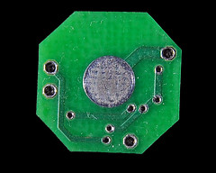
They are here!


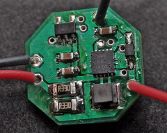
And here it is finished(still need to clean the flux off):

Initial test with a 2V dummy load:
2x .33Ω [.17Ω] = 155mA
2x 1Ω [.5Ω] = 51mA
That means the effective gain on the amp is aprox. 19V !?
Something is wrong, the resulting current should be 1A and 333mA respectively with a gain of 3V. The bench PSU might not have been set up correctly. Ill recheck when I get into work.
UPDATE ... Well, its right there on the INA193 datasheet, output gain is 20V/V. I have to order really tiny value resistors. 0.06Ω for 417mA. But I can use the dual .33's for a 6x BR build


And here it is finished(still need to clean the flux off):

Initial test with a 2V dummy load:
2x .33Ω [.17Ω] = 155mA
2x 1Ω [.5Ω] = 51mA
That means the effective gain on the amp is aprox. 19V !?
Something is wrong, the resulting current should be 1A and 333mA respectively with a gain of 3V. The bench PSU might not have been set up correctly. Ill recheck when I get into work.
UPDATE ...
Last edited:
Rafa
0
- Joined
- Feb 4, 2010
- Messages
- 437
- Points
- 0
Hey hey! Nice!
Thats very cool... Are they stable?
Thats very cool... Are they stable?
jib77
0
- Joined
- Jun 19, 2010
- Messages
- 718
- Points
- 0
Hey hey! Nice!
Thats very cool... Are they stable?
I need to scope it again w/ higher resolution so I can get startup and ripple measurements, but from what I saw during the initial test it looks really good!
erdabyz
0
- Joined
- Jun 30, 2008
- Messages
- 286
- Points
- 0
I need to scope it again w/ higher resolution so I can get startup and ripple measurements, but from what I saw during the initial test it looks really good!
Pretty cool! Yeah, looks good once soldered, very good job there!
I thought you knew you were going to need really small value resistors! That's why I told you that the idea of using a potentiometer in paralel with the sense resistor woudn't work at all, as there are no pots with such low values. I only have 0.1ohm ones on hand right now, and I'm gonna need 5 of them in paralel for my TPS63020 based driver to be able to get some decent current. I can't wait for having more things to order to make another big online order with more proper resistors.
WILLING TO SEE THOSE O'SCOPE PICS!
- Joined
- Aug 7, 2010
- Messages
- 2,086
- Points
- 0
pump 1.5amp using ONE 18650 using one of these, without too much heat, that I'll buy from you (cheap) 
Rafa
0
- Joined
- Feb 4, 2010
- Messages
- 437
- Points
- 0
pump 1.5amp using ONE 18650 using one of these, without too much heat, that I'll buy from you (cheap)
Sure sure.
He will sell you a driver wich gives 1.5A without passing 35ºC for five bucks.
(Tip: Keep dreaming)
jib77
0
- Joined
- Jun 19, 2010
- Messages
- 718
- Points
- 0
pump 1.5amp using ONE 18650 using one of these, without too much heat, that I'll buy from you (cheap)
In boost mode the part can reliably do 5V at 800mA with the input voltage of one Li-Ion cell(3.7V nominal), or 1.2A in buck mode. Doesn't mean it wont if you push it, but the TPS63000 is not rated for that.
Selling ... well if I sell anything it will be just the bare PCB and *maybe* the parts kit. I don't have the facilities or time to build quantities needed to break even. The parts are not exactly cheap in small quantities either, the switcher alone is $4.44, the instrumentation amp is $3.29, the really small value resistors are around $1 EACH, and the filter caps are $0.38. Parts+PCB+Shipping is going to end up around $20.
RoDnSuE
0
- Joined
- Jul 15, 2010
- Messages
- 191
- Points
- 0
Very Nice work Jib.
I've designed a couple of boards before and found I enjoyed the layout process more than the project itself
I used a PCB program called "Layo".
It was a very powerful program, but had a very long learning curve. (at least for me)
Nice Job! +1
I've designed a couple of boards before and found I enjoyed the layout process more than the project itself
I used a PCB program called "Layo".
It was a very powerful program, but had a very long learning curve. (at least for me)
Nice Job! +1
Rafa
0
- Joined
- Feb 4, 2010
- Messages
- 437
- Points
- 0
I recomend you guys ExpressPCB, it's the easiest to use PCB program EVER! At least for me. It's what I use to make all of my PCB's.
jib77
0
- Joined
- Jun 19, 2010
- Messages
- 718
- Points
- 0
Thank you! I too enjoy the layout process the most ... it's like a puzzle, but fun 
I love ExpressPCB! Extremely easy to use and you dont even need to generate a schematic. I use it at work all the time for simple quick stuff like header pitch adapters and connector breakout boards. Sunstone(aka PCBExpress) has PCB123, its supposed to be good but I havn't tried it yet. The only thing is both have proprietary file formats, if you want the gerbers for production runs, you will have to pay them a fee to generate then for you. Eagle is a pain to learn but once you get then hang of it its not bad at all.
Very Nice work Jib.
I've designed a couple of boards before and found I enjoyed the layout process more than the project itself
I used a PCB program called "Layo".
It was a very powerful program, but had a very long learning curve. (at least for me)
Nice Job! +1
I love ExpressPCB! Extremely easy to use and you dont even need to generate a schematic. I use it at work all the time for simple quick stuff like header pitch adapters and connector breakout boards. Sunstone(aka PCBExpress) has PCB123, its supposed to be good but I havn't tried it yet. The only thing is both have proprietary file formats, if you want the gerbers for production runs, you will have to pay them a fee to generate then for you. Eagle is a pain to learn but once you get then hang of it its not bad at all.
I recomend you guys ExpressPCB, it's the easiest to use PCB program EVER! At least for me. It's what I use to make all of my PCB's.

