Welcome to Laser Pointer Forums - discuss green laser pointers, blue laser pointers, and all types of lasers

Buy Site Supporter Role (remove some ads) | LPF Donations

Links below open in new window

FrozenGate by Avery

Planning DIY TPS63000 based driver

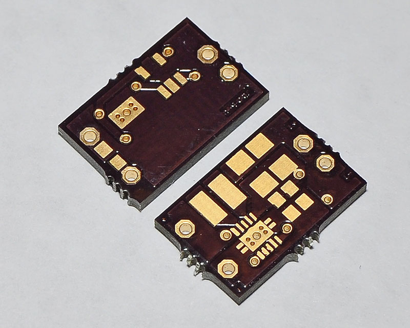
If I sell anything it will be the PCB. If ...
1) I can resolve the heat and stability issues at higher currents
2) you are willing to so some fairly advanced soldering


Yes you mentioned this before :)
I am willing to do soldering but the advanced soldering might be a problem :) Assuming you work out the problems and the driver becomes a good and popular substitute for the popular Dr.Lava's units, what prevents you to make them in bulk cheap and selling for the price of flexmods (or slightly more)?

P.S. I apologize if my question sounds dumb and I'm missing something obvious.

P.S.S Dr.Lava now has the drivers built for him right?
 
Last edited:


Well see how it goes, if there is enough demand I might consider alternatives to a DIY solution. I just saw on sparkfun a tutorial for reflow soldering using a non-stick hotplate. This might be a good solution.

Hot-Plate-Reflow-1.jpg


SparkFun link

It will take a significant order (and cash outlay) to make it cost effective for you guys and me. I just do not have the cash or the time right now to devote to such endeavor. There is also the time its going to take to conduct QC testing, shipping, and dealing with the inevitable dumb-ass that will fry the darn thing b/c they couldn't follow or understand directions.
 
How is that going? Need any help?

Just waiting for V3 boards to come in ... they were mailed yesterday. I should have them early next week :)

I did put 0Ω resistor across the input diode pads and got one stable at 667mA but the other is not ... I looks like its going in and out of thermal shutdown. I didn't even want to try anything higher until I get the new boards.
You may want to place a "micro" HS in the IC.
Like the ones in the graphic card's ram, you know.
 
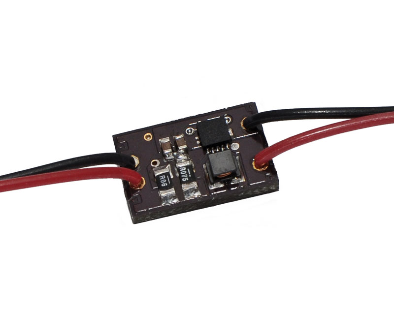
It works! Measured 750mA w/ dummy load and it was still cool to touch!

 
What is the max current it can supply?

The datasheet says 800mA in boost mode and 1.2A in buck mode ... it may do more with heat-sinking since the rating on the internal switches is 1.8A. Right now I don't have the resistor values needed to test any higher.
 
It works! Measured 750mA w/ dummy load and it was still cool to touch!
Congrats on getting it to work!

What was the voltage drop through the load, and for how long could you run it and still stay cool at 750mA?
 
Congrats on getting it to work!

What was the voltage drop through the load, and for how long could you run it and still stay cool at 750mA?

Thanks, the Vdrop was 2.8V IIRC. It ran for around two minutes while I was trying to find my IR thermometer ... didnt find it, but it was still cool to touch when I got back.

Also, FYI ... it fit inside an Aixiz module, but its about 1mm too long with the wires attached.
 
Last edited:
Cut the back of the module off. Many do that.
Great to see you got the power up and kept the working temp so cool.

+1
 
Last edited:
Update ... It does fit Aixiz w/ input wires. With the correct end in(last night I inserted the LD end in ... ooops), the wires are far apart enough that they accommodate themselves with a slight push. :)


Back
Top