Welcome to Laser Pointer Forums - discuss green laser pointers, blue laser pointers, and all types of lasers

LPF Donation via Stripe | LPF Donation - Other Methods

Links below open in new window

ArcticMyst Security by Avery

NUBM0F WOW....

Darktron

Active member
Joined
Dec 9, 2018
Messages
133
Points
43
I like your modules with a pocket for the round drivers..... is it a 17mm round driver board ?
How do you retain your laser diode ? Threaded ring ?
Or are you using a 12mm module head ( diode presses in ) and holding it with that set screw ?
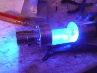
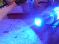
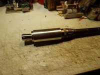
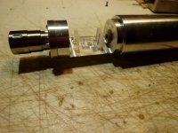
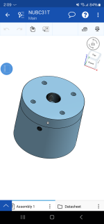
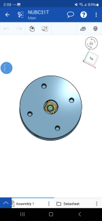
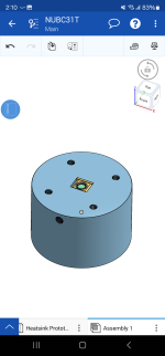
Yes 17mm round driver. The laser diode is pressed into an 12mm aixiz head then aixiz slides into heatsink with thermal paste held by setscrew. Tolerances are kept around 0.03mm from sketch.


Joined
Jul 10, 2015
Messages
9,914
Points
113
I received 2 more re-canned NUBM0F today and put them in 12mm copper modules from Barnett Unlimited with a good quality thermal compound and they both tested 8.2W @ 5A and 8.65W @ 5.5A from a cool start and using the same pair of clean new G2 lenses and testing both diodes with both lenses to prevent any errors which a dirty lens can easily cause.
I think 5A would be a good working current for quasi continuous use in limited duty cycle builds the way we do.
So far my 1st diode is the strongest but not by all that much more.

p.s. I did push to 5.9A from a cool start but could not break into the 9's like my 1st diode did @ 5.7A, however these 2 are close and good for 8W+ as we overdrive them ( limited duty cycles ).
 
Joined
Jul 10, 2015
Messages
9,914
Points
113
I just ordered some 5X beam expanders and 1 will be mated with a nubm0F @ 5A in a c-lens corrected build.

I took the solid back half ( without a pedestal ) off 1 of the 2 nubm0F from my 2nd order ( that would not break 9W not even @ 5.9A from a cool start and put on a pedestal back half with plenty of good heatsink compound and all I can say is DTR and friends knew what they were doing, having tension against the backing plate makes the difference...... how much difference......

Rather than 8.65W @ 5.5A I got 9.34W @ 5.5A that ticked down to 9.24W over about 15 seconds....... it's the positive tension I believe that makes the difference.

SANY7229.JPGSANY7232.JPG

I replaced the back on the 2nd nubm0F with a pedestal back half and it broke 9W as well hitting 9.11W @ 5.5A
There's no doubt the positive tension against the backing plate helps, maybe if the smooth back half could tighten against the backing plate with a fraction of a mm sticking up, this would let us tighten to get positive tension.

SANY7236.JPGSANY7238.JPGSANY7258.JPG
 
Last edited:

Darktron

Active member
Joined
Dec 9, 2018
Messages
133
Points
43
I received 2 more re-canned NUBM0F today and put them in 12mm copper modules from Barnett Unlimited with a good quality thermal compound and they both tested 8.2W @ 5A and 8.65W @ 5.5A from a cool start and using the same pair of clean new G2 lenses and testing both diodes with both lenses to prevent any errors which a dirty lens can easily cause.
I think 5A would be a good working current for quasi continuous use in limited duty cycle builds the way we do.
So far my 1st diode is the strongest but not by all that much more.

p.s. I did push to 5.9A from a cool start but could not break into the 9's like my 1st diode did @ 5.7A, however these 2 are close and good for 8W+ as we overdrive them ( limited duty cycles ).
Suspect them recanned caps are crap
 
Joined
Jul 10, 2015
Messages
9,914
Points
113
Suspect them recanned caps are crap

I suspect when we use pulled/harvested diodes with indium residue on the backing plate that a firm pressure contact patch ( along with thermal compound ) is needed to get the best thermal transfer, also it's a matter of tolerances, both manufacturing of the housing and the diode as well as indium residue, so having a firm pressure contact via. an adjustment span compensates for varying tolerances, especially with pulled diodes.

SANY7275.JPG

p.s. If you have any doubts then test it for yourself, I just ordered some more of these 25mm solid coppers with pedestal backs, they are excellent quality and this is a pretty good price. If you try these you will see that your LPM reading at max over-clock doesn't trickle away as fast. https://www.ebay.com/itm/173869538508?
 
Last edited:

Darktron

Active member
Joined
Dec 9, 2018
Messages
133
Points
43
If you try these you will see that your LPM reading at max over-clock doesn't trickle away as fast.
I could in the future just for giggles but my current design is based on laser manufacturer experience and specs. Works wonders for me that 2.5x5.0mm slot is just barely enough for the 21AWG wires with heatshrink to go through setscrew pushes against aixiz at the perfect angle to get maximum surface area contact with the obvious tolerances that my manufacturer can machine down. Everything fits perfectly tight and no play just a bit of thermal paste will do for the LD base contact to heatsink. I will be getting a ophir head soon so my tests are legitimate😁

Edit: I'll actually get a Gentec head...
 
Last edited:
Joined
Jul 10, 2015
Messages
9,914
Points
113
I've never tested your housing, but they look good. The 5% or so difference at the top end I discovered between the pedestal with adjustment gap unit and the other is specific to those 2 units. I believe I understand now why they were made that way.
 
Joined
Jul 10, 2015
Messages
9,914
Points
113
Well this build I've done many times before, but it's a 9W diode, so I put 1 of these in a host I had on hand with a 6x c-lens pair and beam expander and it's a sweet fire maker across my workshop, the couple of extra watts is noticeable but not drastically so, I think a hand built KE array of at least half a dozen ld's is in order, my only question is how long until we can get the NUBC31 and how much will it cost, these 0F's @ 9W+ are 45 dollars re-canned which is pretty good, but I really want to work with the NUBC31 & it's siblings as the way they will mount has me thinking up some ideas.

SANY7372.JPGSANY7378.JPGSANY7380.JPGSANY7384.JPGSANY7439.JPGSANY7442.JPGSANY7450.JPG
 

Darktron

Active member
Joined
Dec 9, 2018
Messages
133
Points
43
my only question is how long until we can get the NUBC31 and how much will it cost
Still no more info on it and siblings. No cost info yet.
as the way they will mount has me thinking up some ideas
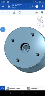
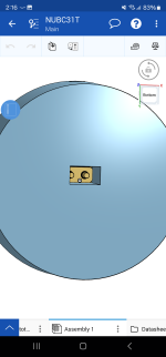
A square hole with a setscrew to add pressure to top plate. I've already got a smaller heatsink in mind but this one was the first prototype heatsink. With regular lenses we commonly use.1000027367.png1000027368.png1000027369.png1000027371.png1000027372.png
 
Joined
May 4, 2009
Messages
2,239
Points
83
What is everyone planning on using for a driver when they do become available?
 
Joined
Jul 10, 2015
Messages
9,914
Points
113
I have an unused black buck 8 in my inventory, also could use one of the Chinese variable PS or use a homemade linear, but I expect Giannis_TDM will come up with something as will others to offer for sale.

-----------------------------

@ Darktron: Sure for a single hand held, fitting to round is fine, but for building an array the smaller flat mount housing is a good thing.
I am also thinking about an X-Y adjustable mount for fine adjustments to make each beam perfectly level, the mount has to have enough surface area to effectively move waste heat without being overly bulky..... I'm thinking copper...... but hopefully the factory tolerances/alignment will be good enough that it won't be needed.....testing is needed.
 
Last edited:

Borislav@87

Active member
Joined
Mar 20, 2022
Messages
355
Points
43
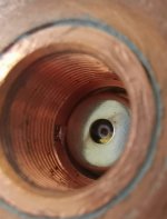
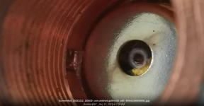
Brand new NUBM0F diode. During a test, after a few minutes of operation, the glass broke. It's not my fault. Whenever I place diodes I work very carefully and cleanly. There is no way a foreign body got inside because the lens was not removed. Probably a defective item. It happened at 5A current. Luckily the diode works. I will try very carefully to remove the protective capsule with the glass. With a small file, I will make a hole where the capsule is stuck and try to peel it off. If it can't be done with the file, I will file the entire capsule from everywhere.
 

Attachments

  • Screenshot_20231212_135516_com.android.gallery3d_edit_409010396502691.jpg
    Screenshot_20231212_135516_com.android.gallery3d_edit_409010396502691.jpg
    607.9 KB · Views: 6
Joined
Jul 10, 2015
Messages
9,914
Points
113
That's a burn through from debris on the window, you can see a smudge from the smoke, also it looks like you have thermal paste around the perimeter and something on the left side too. ( 9:00 clock position )

Screenshot from 2023-12-12 08-38-27.png
 
Last edited:


Top