Welcome to Laser Pointer Forums - discuss green laser pointers, blue laser pointers, and all types of lasers

LPF Donation via Stripe | LPF Donation - Other Methods

Links below open in new window

ArcticMyst Security by Avery

No more reverse polarity protection!

AnthoT

0
Joined
Jan 14, 2012
Messages
2,133
Points
48
Well, as far as I know it some people accidentally damage drivers & diodes by inserting the batteries the incorrect polarity. But not anymore! :D using this you can insert the batteries however you want to as long as you place this device before the driver input, you'll never kill another diode because of batteries ;)

I have a version of this planned to be an 17mm with contact board but I had a bunch of diodes lying around so I figured I could still use them and others can too but for an amazing price! For all of these that I have now they are 1$ each :eek: thats definetly worth the investment of never killing another diode or driver!

Here's some pictures


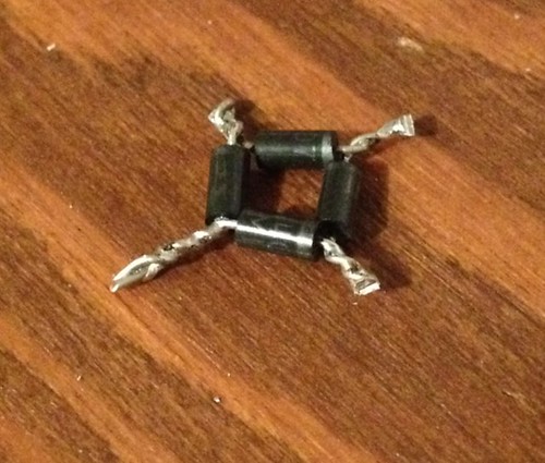
This is what you get for 1$
7250675176_04f46c882c.jpg


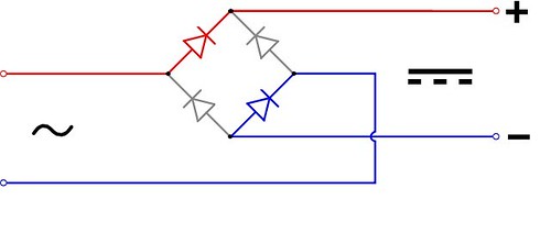
this is how you hook it up
7250676848_4329b1428b.jpg


Here's a demo showing it working :)
Notice when I switch the input polarity it still outputs positive voltage :)

This does drop Aproximately 0.3V though :(

I've got exactly 10 of these so get them while they last :)
 
Last edited by a moderator:


Joined
Sep 20, 2008
Messages
17,622
Points
113
That is a bridge rectifier...
The input still goes through 2 diodes in either input
direction.
There is a Forward Voltage drop through a rectifier
diode. It would be wise to use a Shottky type diode
to lower the Foward Voltage losses...

You also need to choose a diode that can handle the
current required by the Driver/LD..


Jerry

You can contact us at any time on our Website: J.BAUER Electronics
 
Last edited:
Joined
Mar 2, 2011
Messages
692
Points
0
Has to be a Schottky diode. 2 of them in series would be around that voltage.

Schottky diode - Wikipedia, the free encyclopedia

Generaly the ones with an extremely low VF are not the ones that can handle a couple Amps.

Mouser has thousands of diodes for sale, only a handfull are .15v forward voltage. (none of them can do high current)

Currious the spesific one he chose.
or if mabye he meant .3V each, or .6V total
 
Joined
Mar 23, 2011
Messages
2,095
Points
63
That is a bridge rectifier...

Agreed. One of the few diagrams that are still etched in by brain by 2 years of electronics classes way back in high school. The diagram even shows AC on the input. :)
 
Joined
Jan 14, 2011
Messages
424
Points
0
So, the logic seems to work, but how could it be used in the common host types used (where case is the common: as in case negative for a reddie or a blue, and case positive for a green module or IR)? You would have to isolate the case and the heat sink, or the diode itself.
 
Joined
Dec 6, 2008
Messages
1,581
Points
63
The latest Schottky bridge rectifiers only have ~0.44 Volt loss @ 1-2 amps.

Of course, only one Schottky rectifier at the diode . . .

would give polarity protection

LarryDFW
 
Last edited:
Joined
Nov 7, 2008
Messages
5,725
Points
0
Of course, only one Schottky rectifier at the diode . . .

would give polarity protection

LarryDFW


Correct:

6939-reverse-polarity.gif


It's as simple as this (ignore the part numbers above, they are irrelevant, any diode will work): Picture the above as the input connection on an LM317 driver (or any other type of driver), with the driver connected at the right-hand side of the diagram and the DC from the batteries or PSU on the left. If you connect the positive and ground as shown, the connected load will work correctly. If the polarity is reversed the diode diverts all voltage over .3V-.7V (depending on the type of diode) to ground, protecting the connected load. Thus, all that is needed is a single diode.
 
Last edited:

AnthoT

0
Joined
Jan 14, 2012
Messages
2,133
Points
48
Yea forget about this one, it's terrible....

I'll make one with mosfets instead it should be much more efficient
 
Joined
Nov 7, 2008
Messages
5,725
Points
0
Yea forget about this one, it's terrible....

I'll make one with mosfets instead it should be much more efficient

I wouldn't say it's terrible, you shouldn't sell yourself short. What you made is a bridge rectifier which is extremely useful for converting AC to DC. It's just that you overthought the problem of reverse polarity damage, resulting in an overly complicated solution. Happens all the time, which is why engineers have a nice acronym that helps remind us: "KISS" = Keep It Simple Stupid!! lol..
 
Last edited:

AnthoT

0
Joined
Jan 14, 2012
Messages
2,133
Points
48
I wouldn't say it's terrible, you shouldn't sell yourself short. What you made is a bridge rectifier which is extremely useful for converting AC to DC. It's just that you overthought the problem of reverse polarity damage, resulting in an overly complicated solution. Happens all the time, which is why engineers have a nice acronym that helps remind us: "KISS" = Keep It Simple Stupid!! lol..

Lol, I'll just make one with mosfet :) if anyone needs AC to DC convertion I'll let anyone have these for 0.25$ each :)
 

Hiemal

0
Joined
Dec 27, 2011
Messages
1,443
Points
63
Correct:

6939-reverse-polarity.gif


It's as simple as this (ignore the part numbers above, they are irrelevant, any diode will work): Picture the above as the input connection on an LM317 driver (or any other type of driver), with the driver connected at the right-hand side of the diagram and the DC from the batteries or PSU on the left. If you connect the positive and ground as shown, the connected load will work correctly. If the polarity is reversed the diode diverts all voltage over .3V-.7V (depending on the type of diode) to ground, protecting the connected load. Thus, all that is needed is a single diode.

Problem. Then the diode is basically conducting whatever current the battery can muster. Since a diode isn't resistance it will get very, very, hot, very very fast, and will more than likely short/explode/ or go open.
 
Joined
Nov 7, 2008
Messages
5,725
Points
0
More effective, and I'm not sure why I didn't draw this instead (brain fart I guess, was working on a computer at the time), would be to put a diode in series with the + DC line oriented so that current can only flow in the proper direction. Then even if the polarity is reversed no current can flow thus the circuit can't be completed.
 
Last edited:


Top