Welcome to Laser Pointer Forums - discuss green laser pointers, blue laser pointers, and all types of lasers

LPF Donation via Stripe | LPF Donation - Other Methods

Links below open in new window

ArcticMyst Security by Avery

NJG-18, multimode boost driver for 445nm.. and possibly 650nm

Joined
Mar 26, 2010
Messages
3,220
Points
0
Have you ever played with 'circuit'? It's a java based circuit simulator. I have a copy on my webserver but it's available elsewhere on the net.. and you can download it too.

Here's the one on my webserver.

Circuit Simulator Applet

Keep in mind, I didn't write this, the links and all the info point back to the original author.


Joined
Jun 12, 2011
Messages
292
Points
0
Yes I've seen that simulator, but I have a full copy of Tina

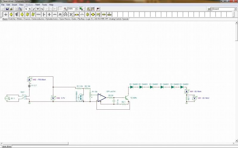
Heres the schematic sorry if its hard to see it every photo host I've tried gives a small image.

driver.jpg


PS Yes, I forgot to connect + to the op amp and the npn just before the laser.
 
Last edited:
Joined
Mar 26, 2010
Messages
3,220
Points
0
You do know that you can accomplish similar things with normal voltage regulator IC's right? The main benefit of the NJG-18 is that it's a boost driver. Opamp driven current sources/sinks aren't. The Vout will always be less than the Vin.
 
Joined
Jun 12, 2011
Messages
292
Points
0
If I may ask, why are we after boost drivers anyway, is it because of teh Vd across the diode and the 1.25Vref for the regulator, and is it for certain diodes because a 445 has a higher Vd then say a 660 or 405?

I'm jsut asking because I won't let the idea of at least a 3 mode variable Current regulator go, and I'm pretty close to have one designed just need to round up a few parts to test it out, the only problem is its limited to being a 1.8-5.5V 3-mode 10mA-1.5A driver, a boost driver with the possiblity of being able to do 1.8-(say 7.4)V single mode 10mA-1.5A driver all on one board, or being 2 boards with both features.
 
Joined
Jan 21, 2010
Messages
935
Points
0
(Everyone, correct me if i'm wrong but i'm pretty sure i'm right - i only recently learnt about drivers)
The issue is, using a Buck for a red means supplying 3V which is no problem. That's 1x 18650, CR123, 14500, 10440 or 2x AA (etc. - there are loads of configurations). No problem at all. But for 445s and 405s it's 5V. That means if we want a reasonably small host our only option is really 2x CR123. And lots of people (me included) dislike CR123.
 
Joined
Apr 23, 2011
Messages
212
Points
0
(Everyone, correct me if i'm wrong but i'm pretty sure i'm right - i only recently learnt about drivers)
The issue is, using a Buck for a red means supplying 3V which is no problem. That's 1x 18650, CR123, 14500, 10440 or 2x AA (etc. - there are loads of configurations). No problem at all. But for 445s and 405s it's 5V. That means if we want a reasonably small host our only option is really 2x CR123. And lots of people (me included) dislike CR123.

Why do you guys dislike CR123s so much out of curiosity? I would think that would be the solution to your voltage issue per size. Here is some basics regarding the names of most used type of power supplies. Sorry if you already know all this.

Power Supply verbiage:

Switching buck regulators only go down in voltage. However, they do so very efficiently and you get current gain. Side effect though on all switching supplies is ripple.

Switching boost regulators can only boost voltage. They do so at the expense of the input current. The require more current in than they put out. They also have a greater degree of ripple than buck supplies and are less common overall.

Buck-Boost (not to be confused with digikeys "Buck, Boost") is a phrase for a switching regulator that can switch independently between bucking and boosting modes by varying the duty cycle of the main switch. More complicated and in many cases this requires a larger circuit topology with 2 inductors. 1 for bucking and 1 for boosting. Some ICs are nice enough to be configured such that you only need 1 inductor but none of those ICs really have the current output pre voltage input that were looking for. Well... atleast that i've seen. Don't be deceived on digikey where you see 100s of drivers that say buck, boost, ..ect. These drivers can only be configured to either buck or boost based upon where you put the main inductor.

Another type of switching supply is called Sepic. It is also like buck-boost where it can both boost and buck voltage. However, i've never taken power electronics yet and haven't studied enough on my own to know how it differs from buck-boost. It does the same thing essentially I believe. Other members feel free to correct me if i'm wrong.

Lastly there is a course linear. Linear is always "buck" and can have a dropout as low as .1V per amp. Maybe lower. So with a linear driver you could supply 2-3A at 3.7ish volts. 18650s measure 4.2V out of the box right? (my first are being shipped out right now for driver development). So you could theoretically pump 2As through a 445nm diode with a linear driver, your voltage though would still be 3.7V. Not sure what happens at that point but i'd assume the diode wouldn't be nearly as bright as pumping 2A at 5V.
 
Last edited:
Joined
Mar 26, 2010
Messages
3,220
Points
0
The micro flexdrive succeeds in doing boost/buck with a single inductor.

The main reason most dislike CR123's is size is fairly well tied to capacity.. With a high power 445nm, etc.. I think most would like longer runtimes on a set of batteries than 20-30 minutes.. Especially if using primaries... That would get expensive in a hurry.
 
Joined
Apr 23, 2011
Messages
212
Points
0
The micro flexdrive succeeds in doing boost/buck with a single inductor.

Yup, the flex drive does have that to its advantage. It has the potential(never did an efficiency test on it) to be very efficient. The Jib boost(boost only to my knowledge) drive won't be able to match its efficiency for powering low power diodes such as a LPC815. Flex drive will beat jib boost and the drive that i'm working on in terms of that. Unless i'm wrong on Jibs being only boost.

However, such ICs that only require one inductor, again, are very limited. The disadvantages of the Flex drive are very limited voltage input range, very limited voltage output range, and a low peak current (1.5A?). Jibs going all boost and so that way he will be able to use a nice boost convertor with a wide input and output voltage as well as a high switch current. Just technically won't be ideal for LPC815s if battery efficiency is coveted above all else. However, its best just to buy a driver specific to diode so in that case a JIB linear should do the trick.
 

ReNNo

0
Joined
Mar 27, 2009
Messages
589
Points
0
These driver are sold out in every shop I know.
Does anyone know where to find these drivers besides KD or DX?
 
Joined
May 25, 2010
Messages
3,655
Points
0
I think i say someone write that they have been discontinued Due to them Exploding.:(

Not sure if that is True though.
 
Joined
Mar 26, 2010
Messages
3,220
Points
0
They've certainly been discontinued, regardless of the reason. I'm trying to work out a boost/buck design to use in my sipiks but *design* is a little different from *repair* (what I do for a living) so i'm having to brush up on my switching power supply theory again as well as change thought processes a little. So that project is not so speedy.
 
Joined
May 25, 2010
Messages
3,655
Points
0
Yea its too bad. They are or "where" great for the money. Just wish i bought more before they did. i only have 1 left. I have not even tested it to see if it works.LOL

I hope it does.

Hopefully they come out with a Better one.:D

Sounds Interesting. Cant wait to see what you make.:D
 
Last edited:
Joined
Mar 26, 2010
Messages
3,220
Points
0
I have maybe 5 left myself. But yeah. Not sure how many of them actually work correctly.
 

DTR

0
Joined
Jun 24, 2010
Messages
5,684
Points
113
I am in the same boat with six untested ones.:eek:

From what I have seen I believe the negative wire hole is too close to a positive lead on the opposite side of the board and if you get too much solder in the hole it it will short. I have done this quite a few times. But I use a power supply to test them and if it starts off drawing 5A from my 5A supply I know that I have shorted it and will turn it off right away keeping the driver from overheating and exploding. And most of the time I am able to desolder the connection and use the alternative hole on the edge of the board without issue. But this means you will not be able to use the modes.
 
Last edited:


Top