I ran the nubm31t all 4 channels parallel at 9.412A for about a minute
CH1: 2.386A
CH2: 2.328A
CH3: 2.436A
CH4: 2.306A
I was thinking of putting a ~ 4A fuse on each channel. Once one blows, the rest will blow immediately.
During testing of the nubm31t, I killed a laser driver which caused around 8.5A to be split between two channels. This unexpected event made me realize the diode should have no problems at 4A when the fuse reaches that point.
I will be running this set up for the time being until something occurs. I had no luck finding a proper high voltage driver that matches the nubm31t. It also needs to be reasonably sized and portable.
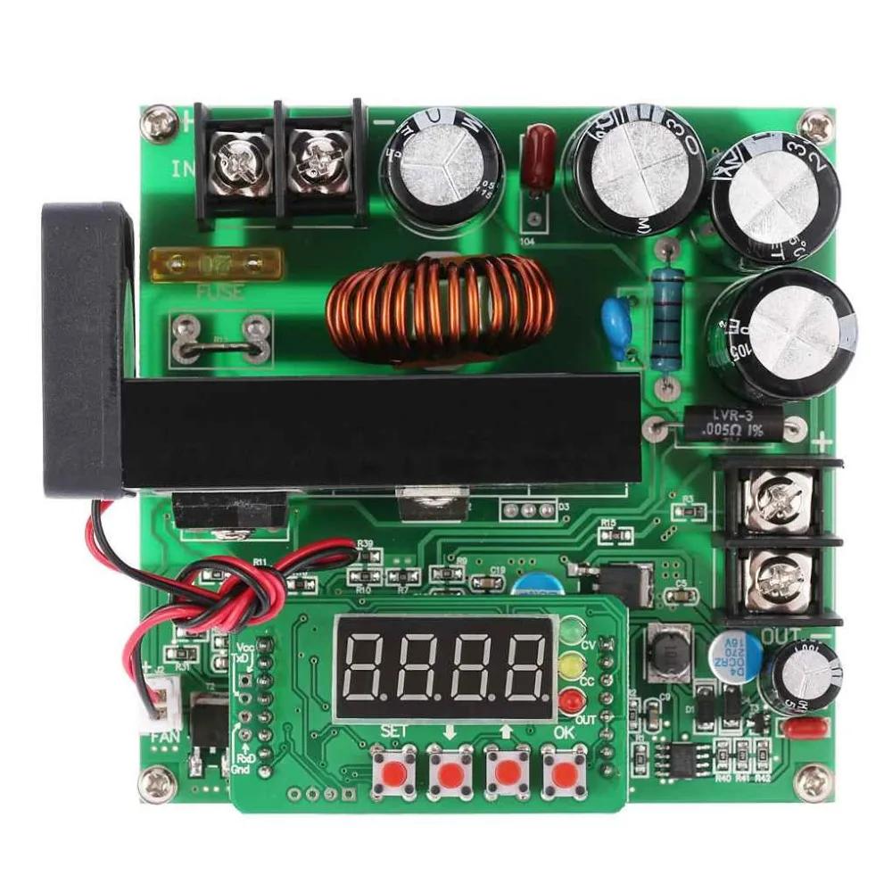
The driver I am using is the Maiman SF6060, 95% efficiency stepping from 52V down to 22V @ 10A. So much better than the other driver I had which did have 3 channels, but just utterly failed past 3A on any channel. It also produced so much heat, but I was not able to measure the efficiency.
____
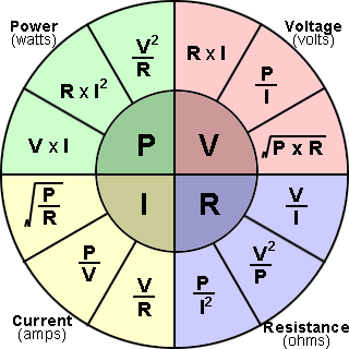
If I were to use a 1ohm resistor across each channel and each channel running at 3A, how much losses would I be getting?
CH1: 2.386A
CH2: 2.328A
CH3: 2.436A
CH4: 2.306A
I was thinking of putting a ~ 4A fuse on each channel. Once one blows, the rest will blow immediately.
During testing of the nubm31t, I killed a laser driver which caused around 8.5A to be split between two channels. This unexpected event made me realize the diode should have no problems at 4A when the fuse reaches that point.
I will be running this set up for the time being until something occurs. I had no luck finding a proper high voltage driver that matches the nubm31t. It also needs to be reasonably sized and portable.
The driver I am using is the Maiman SF6060, 95% efficiency stepping from 52V down to 22V @ 10A. So much better than the other driver I had which did have 3 channels, but just utterly failed past 3A on any channel. It also produced so much heat, but I was not able to measure the efficiency.
____
If I were to use a 1ohm resistor across each channel and each channel running at 3A, how much losses would I be getting?


")