Welcome to Laser Pointer Forums - discuss green laser pointers, blue laser pointers, and all types of lasers

LPF Donation via Stripe | LPF Donation - Other Methods

Links below open in new window

ArcticMyst Security by Avery

Newly Designed DPSS Laser (and TEC) driver

farbe2

Well-known member
Joined
Oct 3, 2018
Messages
303
Points
63
Hey Guys,

i am currently working on a DPSS laser driver that includes two Tec drivers that can heat and cool.

The driver is powered by two 18650 cells and uses step down (Buck) converters to step the voltage down for the TECs and the diode.
That makes it quite efficient, i simulated and calculated something around 95% for the TECs and the diode.

Both included TEC drivers can switch the tec polarity to heat and cool both the diode and the crystal. They can deliver a maximum of 6A into the Tec.
The driver controls the power into the TECs with a PID loop to keep the temperature of the diode/crystal steadily regulated.

Same for the diode drive, it can deliver up to 6A into the pump diode and is electronically controlled.

The driver is powered by a microcontroller and features a display that lets you adjust the set point temperature for both tecs and the laser diode current as well as some other stuff.
There are also all other standard features like:
- battery under discharge protection
- reverse polarity protection
- battery state display
- overheat protection
- sensor error detection

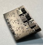
Some preliminary pictures:
bef88b16e94f5eed971d258074f7bc26e29b3d20.jpeg
e6b6c4a349aace0875e9c99e034a0fbf0aa19ad7.jpeg

The best part: the driver is just 39x19mm big!


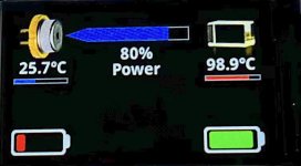
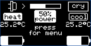
The display interface currently looks like this (but will still change some in future development):
f4e7999cc4bcf6776acb0d531ff1cd8b0bac2e78.png

Showing the battery state, selected pump power level, crystal and diode temp, if the tecs are heating / cooling.
The menu lets the user than select the set point temperature and max diode current.


The development isnt finished yet, however i come close to getting PCBs done for my final version.
So i would like to ask if someone would be interested in buying some of these.
I would than go ahead and order more that i need.
 
Last edited:


Joined
Apr 2, 2009
Messages
10,662
Points
113
please PM me with price you need--outdoors in a cold climate require the TEC to heat.--nice work!! +rep
 

farbe2

Well-known member
Joined
Oct 3, 2018
Messages
303
Points
63
Will do.
However, expect this to take some time.
I am still developing the board. I already changed much from my first post.

The driver now got a color display with adjustable brightness.
and I pushed the efficiency up at low tec voltages.


I drop you a PM when I get done and have all the specifications ready.
 

bd1323

New member
Joined
May 1, 2021
Messages
17
Points
3
I would have interest in a handful of these if priced reasonably fairly
 

farbe2

Well-known member
Joined
Oct 3, 2018
Messages
303
Points
63
Hey bd!

Thanks for your interest.
I dont have a price currently. (more below)
But these drivers are feature packed to the brim and therefore have high parts cost.
We are talking 6 layer boards, >130 components per driver pcb set and 3 PCBs for each "driver".

The development got further so i expand this response into a "whats going on".

I changed the display to something a little more "modern". Its a 1,14" IPS color display with 240x135px. The new display also needed a better microcontroller (which alone costs 7€) to drive the graphics.

The driver now consists of three PCBs.
- the main PCB with all the power electronics, laser driver, two tec drivers and the microcontroller
- the display PCB with the display and an encoder to change settings/navigate the menu
- the power measurement PCB -> consisting of photodiodes to measure relative output power from pump and output beam.

The display will be contacted to the main PCB with a simple flat flex cable.
The Power measurement PCB needs to be soldered.

The driver is still running of 2x LiPo in series.

The current main screen looks something like this:
IMG_1771.JPG

Its still work in progress, so some stuff like the pictures and the diode power graph will still change.

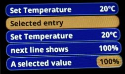
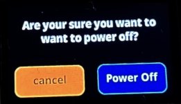
The menu looks like this:
IMG_1745.JPG
IMG_1751.JPG
IMG_1747.JPG

(its very hard to photograph the display without causing moire pattern)

Keep in mind, the menu isnt populated with options. It just shows random stuff to get e feel for the "look" of the menu.

The look is customizable with selectable color schemes. (Two are shown above)

Many settings will be adjustable, like maximum diode current, PID parameters for the tec controller, empty battery thresholds, standby time, menu color.

The driver will get options to select modes (flash/blink/fade).
And will also offer a alignment mode that helps the user to align the laser they have the driver connected to.
That mode will make use of the power sensors to see if a set point temperature change actually increased or decreased the output / absorbed pump power. The driver will display graphs with data from the power sensors.


Pricing:
I am still not finished developing this thing. So there is still stuff open. However i can already say: It won't be cheap.
The parts alone will be more than 50€ per driver set (all 3 pcbs), me placing >130 parts spread over 3 boards will also take a while and including the time spend programming, it gets expensive fast.
So we are talking very roughly 200-250€ per driver set.
Keep in mind that this is a high efficiency, high quality, advanced laser driver for a handheld with many features, not a cheap Chinese battery wasting, diode killing, 2.50$ aliexpress unit.
 

bd1323

New member
Joined
May 1, 2021
Messages
17
Points
3
Hey bd!

Thanks for your interest.
I dont have a price currently. (more below)
But these drivers are feature packed to the brim and therefore have high parts cost.
We are talking 6 layer boards, >130 components per driver pcb set and 3 PCBs for each "driver".

The development got further so i expand this response into a "whats going on".

I changed the display to something a little more "modern". Its a 1,14" IPS color display with 240x135px. The new display also needed a better microcontroller (which alone costs 7€) to drive the graphics.

The driver now consists of three PCBs.
- the main PCB with all the power electronics, laser driver, two tec drivers and the microcontroller
- the display PCB with the display and an encoder to change settings/navigate the menu
- the power measurement PCB -> consisting of photodiodes to measure relative output power from pump and output beam.

The display will be contacted to the main PCB with a simple flat flex cable.
The Power measurement PCB needs to be soldered.

The driver is still running of 2x LiPo in series.

The current main screen looks something like this:
View attachment 74972

Its still work in progress, so some stuff like the pictures and the diode power graph will still change.

The menu looks like this:
View attachment 74974
View attachment 74975
View attachment 74976

(its very hard to photograph the display without causing moire pattern)

Keep in mind, the menu isnt populated with options. It just shows random stuff to get e feel for the "look" of the menu.

The look is customizable with selectable color schemes. (Two are shown above)

Many settings will be adjustable, like maximum diode current, PID parameters for the tec controller, empty battery thresholds, standby time, menu color.

The driver will get options to select modes (flash/blink/fade).
And will also offer a alignment mode that helps the user to align the laser they have the driver connected to.
That mode will make use of the power sensors to see if a set point temperature change actually increased or decreased the output / absorbed pump power. The driver will display graphs with data from the power sensors.


Pricing:
I am still not finished developing this thing. So there is still stuff open. However i can already say: It won't be cheap.
The parts alone will be more than 50€ per driver set (all 3 pcbs), me placing >130 parts spread over 3 boards will also take a while and including the time spend programming, it gets expensive fast.
So we are talking very roughly 200-250€ per driver set.
Keep in mind that this is a high efficiency, high quality, advanced laser driver for a handheld with many features, not a cheap Chinese battery wasting, diode killing, 2.50$ aliexpress unit.
That's all exactly what I was hoping to hear - A well designed, high quality driver assembled by someone that cares about what they are doing. And love the feature set. The anticipated price seems very reasonable as well - looking forward to seeing it progress!
 

farbe2

Well-known member
Joined
Oct 3, 2018
Messages
303
Points
63
Lets do a quick update on my progress so far.

I got the new PCBs, the color screen looks gorgeous.

I got almost every function i intended to program ready.

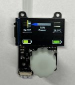
A quick look onto the display board. (dont look too closely, its my prototype board, so no pretty soldering here..)

IMG_1881.JPG

This picture also shows the preliminary splash screen. Its very minimalistic but shows all relevant states of the laser driver / laser.
The power bar is obvious, it also shows if something is wrong that causes the laser to only output reduced power.
The color of the "18% Power" text gets red if something if overheated.

The temperatures beneath the components (tec/crystal) show how hot each component is. This text also gets set to red (too hot) / blue (too cold) depending on the deviation between set point and actually component temperature.
That makes it easy to see if a tec is struggling to keep a component at set temperature.
The small graph below the "24,3°C" is filled depending on the tec power currently used to hold / try to achieve the temperature.
Its also red/blue depending on the tec cooling or heating.
So this picture above shows that around 1/4 of max heating tec power is needed to reach the set point temp and that all temp sensors (case / diode / crystal) are inside the safe range / the output power is currently not reduced.

Batteries are also obvious. The change there color and fill percentage based on current battery level. If the battery level gets to low, the unit will switch itself off.

Every level is adjustable with the menu system which can be accessed by pushing the encoder button and looks like this:
IMG_1882.JPG

All the "second level" menus are reachable from here. The display scrolls to show all options.
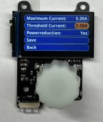
Like setting display brightness/color or setting the PID control parameters for the crystal/pump diode:

IMG_1883.JPG

Kp/Ki/Kd is obvious, same as the set temperature. Offset is used to calibrate the real world temperature to the measured temperature.
Max difference is used to disable (or reduce the power) of the pump diode to protect the laser.

The laser diode menu lets us set the max and threshold current and if we want to only reduce the power progressively while the unit starts to overheat or if we wish to switch it off completely.

IMG_1885.JPG

The save function, saves the current values to the microcontroller. These values are sustained between battery changes and power offs.


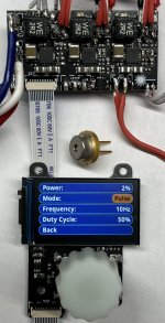
The pump diode is enabled by a separate "fire" button. This one works like on any other boring pointer: While the button is pressed it enables the laser diode current with its current mode and power setting.
Double pressing, latches the diode on until its pressed again.

The current modes are just continuous, flash (with adjustable frequency) and pulse (with adjustable frequency and duty cycle).

Thats it so far.

Just to have a bit better scale of this thing:
IMG_1889.JPG

Thats a 9mm diode!

The driver is 6mm thick, and 39x20mm
The display board is (with display and mounting holes) 31 x 41mm with a thickness of 5,5mm.

The driver is very efficient. Pushing 6A into a blue laser diode without cooling is no problem. The hottest part gets to around 65°C in this condition. Same efficiency for the tecs. I did not measure it but calculations show that it should be above >95% at full load.
I trust these values as the thing is essentially stone cold driving a 4A load with a 1-2 A into both tecs.

It can handle the full 6A on all channels. So 6A for each tec and 6A for the diode max.
The back side of the driver can be used to glue it onto a housing/heatsink which should be enough to drive 3x 6A continuously.
 

CurtisOliver

0
LPF Site Supporter
Joined
Jun 12, 2015
Messages
7,610
Points
113
I can vouch for the amount of time and thought farbe has put into these. They are not cheap drivers, but they'll be worth every penny/cent based on what they can do.
 

Im Greek

Member
Joined
Sep 23, 2022
Messages
36
Points
8
Lets do a quick update on my progress so far.

I got the new PCBs, the color screen looks gorgeous.

I got almost every function i intended to program ready.

A quick look onto the display board. (dont look too closely, its my prototype board, so no pretty soldering here..)

View attachment 75028

This picture also shows the preliminary splash screen. Its very minimalistic but shows all relevant states of the laser driver / laser.
The power bar is obvious, it also shows if something is wrong that causes the laser to only output reduced power.
The color of the "18% Power" text gets red if something if overheated.

The temperatures beneath the components (tec/crystal) show how hot each component is. This text also gets set to red (too hot) / blue (too cold) depending on the deviation between set point and actually component temperature.
That makes it easy to see if a tec is struggling to keep a component at set temperature.
The small graph below the "24,3°C" is filled depending on the tec power currently used to hold / try to achieve the temperature.
Its also red/blue depending on the tec cooling or heating.
So this picture above shows that around 1/4 of max heating tec power is needed to reach the set point temp and that all temp sensors (case / diode / crystal) are inside the safe range / the output power is currently not reduced.

Batteries are also obvious. The change there color and fill percentage based on current battery level. If the battery level gets to low, the unit will switch itself off.

Every level is adjustable with the menu system which can be accessed by pushing the encoder button and looks like this:
View attachment 75029

All the "second level" menus are reachable from here. The display scrolls to show all options.
Like setting display brightness/color or setting the PID control parameters for the crystal/pump diode:

View attachment 75030

Kp/Ki/Kd is obvious, same as the set temperature. Offset is used to calibrate the real world temperature to the measured temperature.
Max difference is used to disable (or reduce the power) of the pump diode to protect the laser.

The laser diode menu lets us set the max and threshold current and if we want to only reduce the power progressively while the unit starts to overheat or if we wish to switch it off completely.

View attachment 75031

The save function, saves the current values to the microcontroller. These values are sustained between battery changes and power offs.


The pump diode is enabled by a separate "fire" button. This one works like on any other boring pointer: While the button is pressed it enables the laser diode current with its current mode and power setting.
Double pressing, latches the diode on until its pressed again.

The current modes are just continuous, flash (with adjustable frequency) and pulse (with adjustable frequency and duty cycle).

Thats it so far.

Just to have a bit better scale of this thing:
View attachment 75032

Thats a 9mm diode!

The driver is 6mm thick, and 39x20mm
The display board is (with display and mounting holes) 31 x 41mm with a thickness of 5,5mm.

The driver is very efficient. Pushing 6A into a blue laser diode without cooling is no problem. The hottest part gets to around 65°C in this condition. Same efficiency for the tecs. I did not measure it but calculations show that it should be above >95% at full load.
I trust these values as the thing is essentially stone cold driving a 4A load with a 1-2 A into both tecs.

It can handle the full 6A on all channels. So 6A for each tec and 6A for the diode max.
The back side of the driver can be used to glue it onto a housing/heatsink which should be enough to drive 3x 6A continuously.

Man it's a progress, you can make process of using laser laser is more durable, safe and comfortable. No one yet have it in lasermakers
 
Last edited:

farbe2

Well-known member
Joined
Oct 3, 2018
Messages
303
Points
63
I managed to build the graph function that should help to align the dpss and should make temperature tuning easy.

3c1154f9e0f6950138a919c524b221fd4a9ae179_2_354x500.jpeg

It draws a graph that shows the absorbed pump power and the output power simultaneously.
You can set the crystal and laser diode temperature and also the laser diode power directly in the graph menu.

It should be very easy to see if the output power is rising/falling while changing temperatures.

The driver has two inputs for photodiodes to measure these powers.
 

farbe2

Well-known member
Joined
Oct 3, 2018
Messages
303
Points
63
Hey Guys!

I just want to let everyone know: the thing is finished. If anyone wants one, contact me.
Don't expect them to be cheap. We are talking >200€ here.

But its (currently) the only driver capable of driving two tecs in heating and cooling mode, while being able to drive up to 6A into a laser diode from two lipos.
Its also the only hobby laser pointer driver with a full color display and full GUI while being very small -> 39x20x6mm for the driver.
The display is a 240x135 1,14" display.
 

kecked

0
Joined
Jun 18, 2012
Messages
952
Points
63
Any chance for the ability to use one menu on three drivers for rgb?
 

farbe2

Well-known member
Joined
Oct 3, 2018
Messages
303
Points
63
Not really. That would make a redesign necessary.
However I already did a RGB driver with a simple menu interface to select colors and have some modes. It doesn't have a display trough.
Here is the build log:

And thats the driver post:

(thats just fro three diodes without a TEC)


Top