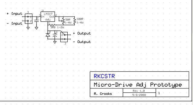
Thought I'd repost the last page of discussion from this topic, as I still had the page up from before the crash. It's still missing some of the third page, including my post about a protoype driver I made up, but it's not really working well yet, so I won't bother. I also talked about a boost driver I made, which is where this kind of starting. Anyway, here it is:
rkcstr
Quote from IgorT on Yesterday at 4:56pm:
I was also thinking of using a 5V boost circuit for blue rays initially. But there are some, that actually have a higher Vf.
But such simple boost circuits really can be made tiny.
Hmm, yeah, that would be a problem. But, out of the 11 I've had, all were between 4.3 and 4.9V, so I'm guessing that's relatively rare? What do those burner diodes run at?
IgorT
I don't remember about the burner diodes for sure, i think it's higher. But when i power my blue rays with 220mA they take like 5.4V or so. (their treshold jumped and they are now undead)
Besides, burners absolutelly require current regulation, especially when a diode costs like $400.. You can't get away with voltage regulation there. You don't want a $400 thermal runaway..
Gazoo told me 5V is enough for any blue ray reader tho, and then he suddenly had one, which didn't work untill he replaced the 7805 with a 317 and saw more than 5V at the usual current.
I hope it's rare or even related to ESD or other damage, like with mine..
rkcstr
haha... diodes of the undead! Yeah, I don't know, I gotta take some of my "dead" ones and see if I can make them undead, lol! See what voltage they run at.
IgorT
I use the Frankenstein method.. 1.6A seems to do the trick, and brings them back to life.. After that, the treshold is above 200mA and the power is very low, but they still make a beam with some fog. enough so, that i was able to take pictures of it.
rkcstr
Well, I took one of my "deader" diodes, that didn't lase very well at 40ma... hooked it up to my prototype driver so I could adjust output. Well it was actually lasing well at about 70mA (but with those crappy artifacts that damages ones have), so I turned it up and definitely killed the thing around 100 something. Well, kept turning it up, about up to 220mA (where the driver pretty much maxed) and it was lasing again, but not very brightly. At ~30-40mA input (no output), it was at about 4.7V, but turning it up to ~150-200mA, the voltage jumped to about 5.9V! It was probably causing the regulator to dropout at that voltage (needs +1.4V, but I'm only feeding it 6.3-6.5V, or about +0.5V), because the output wouldn't really go above 160mA at that point.
IgorT
Yeah, that sounds about right. Mine also stopped lasing at 40, had to use 70, but it died itself, and after that i just didn't care anymore and turned up the current on my PSU to 1.6A (seriously) and then the lasing treshold was 220.
Looks like at least they die consistently..
And i think the voltage was also close to 6V. I still use it occasionally for testing, and if i heatsink it well, it doesn't mind the currents. From this point on it doesn't get any worse, but drops in brightness with heat, as usual.
Kenom
I was going to recommend some Kind of current adjustability on yoru drivers. Even the current one that works well would benefit from a potentiometer. some means of adjusting the current.
rkcstr
My original design had a potentiometer, but I found a problem. When operating at high current output, the power dissipation of the potentiometer is too high. When running at 400mA, it's disspating 1/2W. Also, since the driver tends to run hot, the increased operating temperature also decreases power handling capability. Combine that with the fact that any pot small enough to fit my driver isn't rated more than 1/4W, I felt it was too much of risk to include it, and instead use 1W worth of resistors to set it manually, just to be safe.
Reason for my paranoia is most due to a test of my original circuit which I had going at about 315mA, a small pot (really underrated at 0.1W) controlling the current failed and took my open-can diode with it. While a 0.25W pot would certainly hold up longer, I don't want to risk someone blowing a diode with my driver.
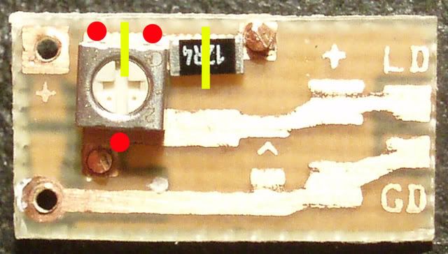
But, it is possible to modify one of my drivers to use a 3mm pot (though I obviously won't recommend it) by removing the resistors, making two cuts on one of the resistor pads and putting the pot and a series resistor on there. Here's a pic of how that would work:


