Welcome to Laser Pointer Forums - discuss green laser pointers, blue laser pointers, and all types of lasers

Buy Site Supporter Role (remove some ads) | LPF Donations

Links below open in new window

FrozenGate by Avery

Micro laser driver - fits Aixiz/DX modules

pseudolobster said:
No worries, I'll check everything over with a mulimeter when I get home and try it out with a dummy load before trying again.

Alright, let me know how it goes because I'm really curious as to what's going on.

Also, have you tried the other, is it working OK?


No, I'm at work right now... I was just really anxious to try my BR this morning when I got them...I'm wondering if I should have been more patient... :P

Anyways, for a dummy load, is there a specific value I have to reach, or will just any handful of random diodes draw the right current? I have some silicon diodes I bought from ratshack a long time ago but I don't know exactly what they are. I also have some near-uv LED's I can use.. they have the same voltage/current draw as white LEDs. (the only dummy load schematic I've found here suggests green LEDs which I know to be lower voltage than whites)

also, the diodes, do I wire them in series or parallel?

Thanks for all the quick responses btw, you've been a great help and it's nice to see someone who stands behind their product like that.
 
Haha, I understand... I should be studying for a final I have Thu  :P

Well, for testing that the regulator is actually regulating, ie doing its job, it doesn't matter what output voltage you test it with, so long as it's >1.25V, it'll put out the same current no matter the output voltage.  I'd suggest 4x standard rectifier diodes (the 1N400x series is one example, but there are others), or a single bright LED I think should have enough forward voltage to do it.  Multiple diodes would need to be in series with each other, with the striped ends being toward ground.  For an LED, if you look at it from the side, you see two little ends of the input leads (inside the diode), the larger ended one is connected to ground, smaller to positive.

http://www.bcae1.com/led.htm

Just make sure you're measuring current as you test so that you can make sure it's not going really high and going to do something like already happened.  I'd also suggest doing the test for shorts before load testing, just to rule that out beforehand.
 
Well, I don't know. I really just don't know.

It seems to work just fine, though maybe my resistor's value is off by a bit.. it starts off at 32mA and slowly creeps up to 33mA where it stays hovering within 0.1mA's... I really don't know. Maybe I shorted the laser's leads somehow, though I highly doubt it, I was pretty sure I got them right when I first soldered them, then confirmed with a magnifying glass... The mind boggles...
 

Attachments

  • DSC00452.jpg
    DSC00452.jpg
    66.2 KB · Views: 194
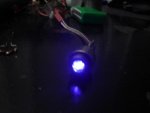
update: HUGE SUCCESS

more updates: Tried the other driver, it works great, very reliably stays at 350mA and my short open can seems to have no problems with it.... the BluRay is now a zombie... I played around with it for about 5 mins before the battery connection started to go loose.. power disconnected and reconnected a couple times and I noticed the bluray being a lot brighter for half a second after power was reconnected.. this happened a couple more times and the beam went much dimmer with yellow artifacts

In summary: Good drivers, well worth the price. watch out for short circuits and wiggly power connections though. Would buy again.
 

Attachments

  • DSC00454.jpg
    DSC00454.jpg
    38 KB · Views: 215
Haha, I'm glad you got it working, that's great!

Again, my guess was there was just a really tiny short somewhere that was difficult to notice.  If you don't use flux applied to an area before soldering, sometimes very tiny bits of solder can cause a bridge between two points, so I always use lots of flux and closely inspect the joint afterward.

Also, it's possible the + pad could have shorted to the case on the diode if it was pushed right against the diode.  I try to cut the boards so the pads are just very slightly recessed, but it's tough to make exactly perfect cuts with my board cutters (some hobby scissors  ;D) and it may leave an edge of the pad against the edge of the board.  Typically the diodes are slightly recessed within the housing anyway which prevents this, so I've never had a problem, but if the diode isn't pressed in fully or just solderd directly to the board while not in a housing, a short is possible.  

So, this is why I always suggest testing for shorts on the output after soldering the diode in to be sure none of this is happening.  

Edit (in response to update in your post):  Sorry to hear about your diode... not sure why that would happen, though.  Good connections are definitely recommended, but I don't think the battery connection would do that.  I wonder if the output capacitor was damaged in whatever happened before?  It should smooth out transients associated with an intermittent power connection.
 
Hey rkcstr,
Any idea on what would be causing the driver to be putting out well over 300mA regardless of the resistors used? This was originally a 38mA driver (one of the very first batches) and I added a couple resistors to change the current to 120mA for my 6x. All appeared to be well, but then I put some fresh batteries and and poof went my 6x diode :'( So i measured the current and it was around 300mA. I thought "ok the voltage was too low, the driver was out of regulation when I tested the resistors etc etc" but then I tried it at just the 38mA setting with brand new batteries and I got the same thing, 300mA. Luckily I had another driver, so I just changed the resistors out, got another 6x drive and hooked it all up (working great by the way) but i still cant figure out why that driver was cranking out that much current. I've looked it over about a million times and still cant see anything out of the ordinary. Thoughts?
 
GooeyGus said:
Thoughts?

Did you measure the resistance across the resistor pads? It sounds like something is lowering the resistance across the pads, so if it measures around 4.2 ohms, that's why you're getting 300mA out. Outside of the likely problems, check for shorts between the output positive and ground, between all connections of the regulator chip and between the positive and negative inputs against each other as well as the non-connected pads nearby (ie the adj pin and output of the chip). Those measurements will give some indication of whether there's a short on the board or one of the parts is internally shorting.
 
rkcstr said:
Edit (in response to update in your post): Sorry to hear about your diode...

Meh, I can always just change some resistors and live with some ugly yellow artifacts.. or better still, I have a 803t sled here waiting to be harvested...

I kinda figured something was wrong once that started happening... A properly constructed driver should compensate for stuff like that (but who knows what fried when that trace blew).. I should have had the presence of mind to disconnect it the first time it happened, but ce'st la vie, we learn from our mistakes.

In other news, the 350mA driver is working just fine, though I've been having to run it at a shorter duty cycle than I'd hoped (30-45 sec)... it seems the resistors are heating up like crazy.. would it help to solder another 4 in parallel? I suppose it wouldn't be too hard to stack them.

Gus: [smiley=shocked.gif] [smiley=cry.gif] eep! it sucks to hear about your 6x.. though it puts my loss into perspective... I hope you didn't pay too much for it, though I suspect you may have :-/
 
Yeah, I'm guessing something else got damaged considering the amount of current that must have passed through that trace.

Anyway, as for the 350mA, as with any of the high output driver, the nature of these linear drivers means that to have them at this size means a sacrifice in continuous use since the copper pad on the board is much smaller than the suggested effective heatsinking.

The reason the resistors are heating up is because the heat is being conducted from the regulator chip to the resistors since they're directly connected to the heatsinking copper on the other side. The actual power dissipation of the resistors is about .473W, but there are 1W worth of resistors on there.

In reality, the board is not going to die at the high temps it runs, but it may cause damage to the laser diode if it gets too hot. I've run my 400mA test board for well over 5 minutes many times while testing (including while connected to an open-can red diode). It peaks around 115-120C, which is above the boiling point of water, lol, but below the shutdown point of the regulator chip.

I have made a few custom boards for another member which implements a heatsink, but the design is too large to fit within the modules, although the peak temp is around 90C in contrast to 120C without the heatsink.

I'm also working on a possible custom option for the drivers which will allow the regulator chip to be thermally connected to a large heatsink like Jayrob's piece for the MXDL or other external heatsink. Basically all that I need to do now is to find a good way to manufacture the small piece of aluminum that is needed to interface between the regulator and Jayrob's heatsink (I have a good idea, i just need to try it), but if you had your own heatsink (it would require thermal epoxy for mounting), the design will work as is.

For my [soon to be] new adjustable drivers

I got the parts today and have been doing some tests and everything seems to be running well. I've worked out the "instability" that was occuring with the lower ranges. Adding the corrective capacitor before would negatively impact the upper ranges, but adding a larger capacitor fixes that problem.

So, the max output seems to be around 430mA, which is just about exact to my estimates considering a minimum resistance of 0.2ohms for the pot and a 2.7ohm series resistor making an effective 2.9ohms. The minimum should be around 27mA for the full- range and low-range settings, while the high-range will be around 150mA or so.

I still need to do an endurance run at maximum output and half max (to test the pot's ability to handle it's peak power), but with my previous prototype rig I ran it for about 22 min. or so with no problems, so I'm confident I will have the same results with the actual parts.
 
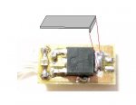
What do you think of something like this?

I cut a fin off a computer heatsink and bent one end at a 90 degree angle and was trying to solder it to the regulator... I was having some problems getting solder to stick to the aluminum, but if I were to try again with, say, some copper sheet metal, do you think it would provide adequate sinking?

The other thing I considered is the rubbery thermal pads they use on some (especially older laptop) cpu's... it's like half rubber, half lead, and doesn't conduct electricity. Under pressure, it conforms to the components underneath. I was thinking of cutting some layers of it, stacking them, and wrapping them with fine wire to hold it to the board. If I play my cards right I should be able to make a nice cylinder that fills the aixiz module.
 

Attachments

  • heatsink_001.JPG
    heatsink_001.JPG
    14.6 KB · Views: 324
So I did some testing... I checked resistance across the pads and you're right, it is exactly 4.2 ohm. I cant figure it out though. I'm using a 10.5ohm resistor. This is so confusing!
 
pseudolobster said:
What do you think of something like this?

Any type of extra heatsinking will help. But, the only problem with heatsinking is the connection to the chip which is heatsinked is connected to the output (positive), so you have to be careful of the heatsink touching the case (which is grounded, negative), if that happens you quite possibly will destroy the driver and/or your laser diode.

You'll have a tough time trying to get solder to bond to the aluminum. You'd probably be better to use solder wick to removed the excess solder from the tab on the chip to create a flat surface for mounting the heatsink and using thermal epoxy. Or a copper heatsink would work as well. Also beware that you don't short the output to any of the "extra" pins on diodes, I'm not sure if it would cause any problems, but don't want to find out.

A simple way to improved the heatsinking would to simply mount a small piece of aluminum between the regulator and board. It's not going to do a lot, but it will improve operating temps some. You just have to make sure the aluminum isn't too thick (1/8" stock may work, I'm not sure), or it won't fit in the Aixiz housing (if you're using something bigger, then there's probably less worry).

GooeyGus said:
So I did some testing... I checked resistance across the pads and you're right, it is exactly 4.2 ohm. I cant figure it out though. I'm using a 10.5ohm resistor. This is so confusing!

Like I've said previously make sure there are no short between areas on the board. But, also check the regulator side of the board, looking between the leg of the chip right next to the negative input, this is the adj. pin, and look for any small solder bridges between that pad and the surrounding pad, which is the output.

But, it just seems odd the output is consistently 4.2ohm. Have you tried measuring without any resistors on there?
 
Just a quick question. I've been thinking of making an MXDL build one of these 38ma drivers. But I don't know what to run it on. I think jayrob said these batteries are good
http://www.dealextreme.com/details.dx/sku.974
But that's for DDL's driver, would 3 of these batteries be too much for this driver?
 
Hmm... after the 38mA driver zombified my diode, I decided to hook some different resistors to it and see how far I could push it....

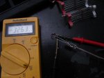
Before I removed the 33r0, I did a quick check with my multimeter, and it seems the old resistor was only providing 1.8 ohms resistance... (this was in-circuit, I haven't checked it by itself yet, it's in the bottom of my sponge I guess).. I shrugged that off and soldered in a 25r5 (or whatever the next lower resistor is, I'm going from memory), powered it on with 4 diodes attached, nothing happened, 0mA. so I checked the resistance of the newly soldered resistor and was dismayed to find it was offering 1.6ohms of resistance. I went around all the traces with an exacto knife to ensure there were no shorts

I suppose something important has been fried, but do you know why the resistors would be doing that?
 
nvmextc said:
Just a quick question. I've been thinking of making an MXDL build one of these 38ma drivers. But I don't know what to run it on. I think jayrob said these batteries are good
http://www.dealextreme.com/details.dx/sku.974
But that's for DDL's driver, would 3 of these batteries be too much for this driver?

You should be OK with two of them for my driver. The average output voltage of two is right around the minimum voltage for my driver, but you should be fine. You can just use two in one of those 3x AAA battery holders and either use a dummy battery (anything to short out that extra battery port) or some others have actually just mounted the driver in that extra space.

pseudolobster said:
Hmm... after the 38mA driver zombified my diode, I decided to hook some different resistors to it and see how far I could push it....

Before I removed the 33r0, I did a quick check with my multimeter, and it seems the old resistor was only providing 1.8 ohms resistance... (this was in-circuit, I haven't checked it by itself yet, it's in the bottom of my sponge I guess).. I shrugged that off and soldered in a 25r5 (or whatever the next lower resistor is, I'm going from memory), powered it on with 4 diodes attached, nothing happened, 0mA. so I checked the resistance of the newly soldered resistor and was dismayed to find it was offering 1.6ohms of resistance. I went around all the traces with an exacto knife to ensure there were no shorts

I suppose something important has been fried, but do you know why the resistors would be doing that?


Back
Top