Welcome to Laser Pointer Forums - discuss green laser pointers, blue laser pointers, and all types of lasers

Buy Site Supporter Role (remove some ads) | LPF Donations

Links below open in new window

FrozenGate by Avery

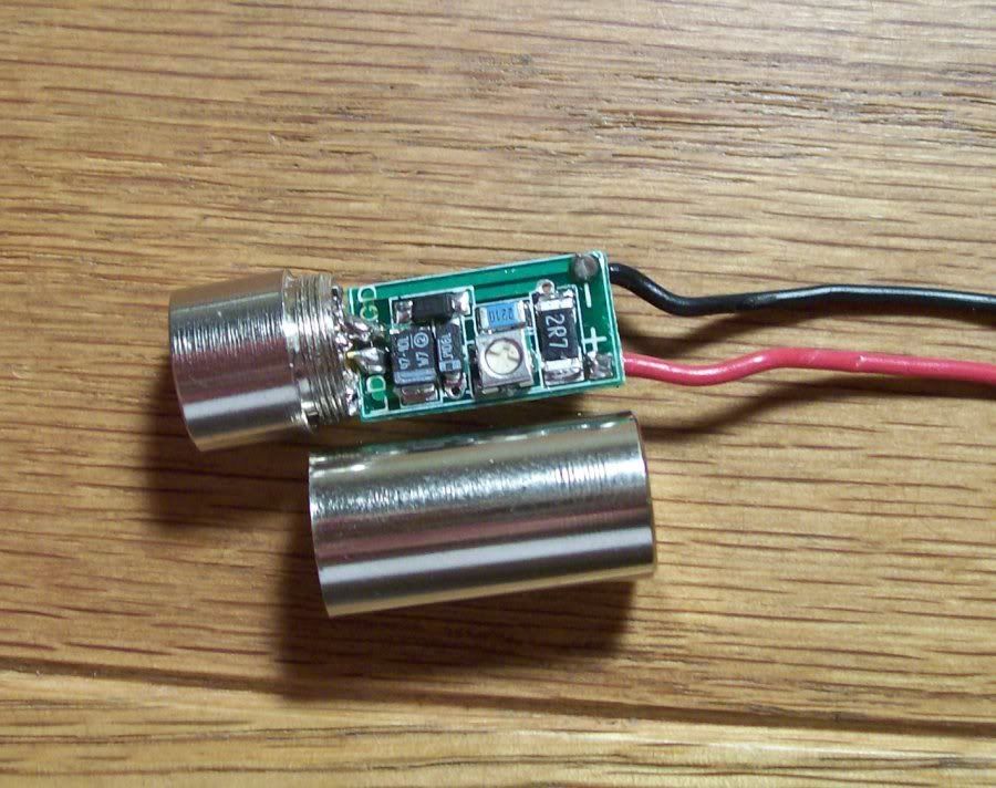
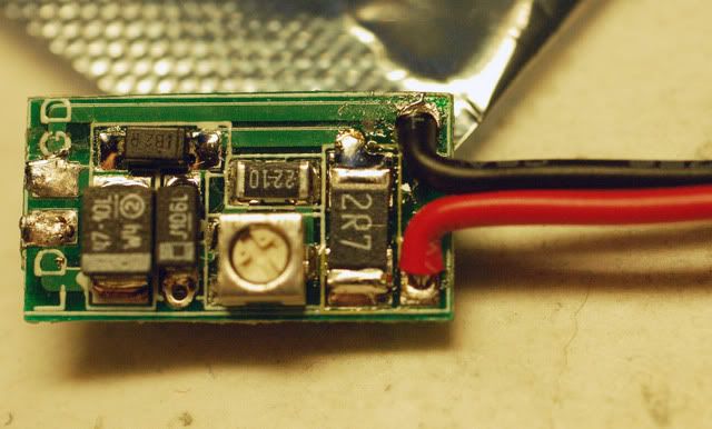
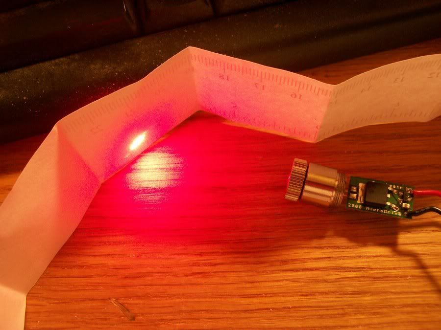
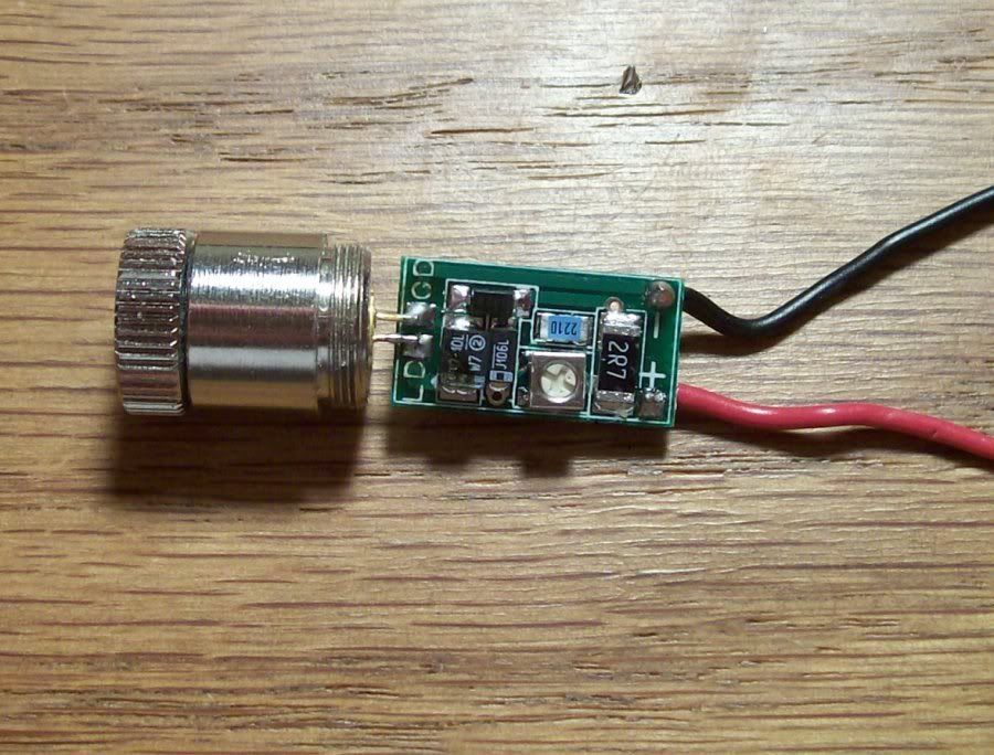
Micro-Drive laser driver by rkcstr

Right now it's just studies... got a couple years until residency :)

Exam next Tuesday and some other stuff that week, so I may start taking orders again that weekend.

I'm still trying to work out the possibility of having the boards manufactured since I have very little free time anymore. So, I'll probably only offer a small amount per week until I can get that figured out. Once that happens, I'll still be very busy, but it will really only be a matter of finding time to mail them out (which can still be time consuming).

There may be a lot of changes in my offerings in the near future and I'll keep you all updated.


Quick simple question here. I thought I had the right screw driver for the pot, but it turns out I was way off. What size should I use for this? Is there any term for the right size so I can go pick one up at my hardware store and ask for the exact right one?
 
It looks like a cross (phillips head), but it isn't since it doesn't have a recessed point in it. Rather, a small flat-head screwdriver is necessary. One of those eyeglass screwdrivers would probably work. The head width just has to be short enough to fit.
 
Ok thanks.

Also, how the heck does anybody manage to mash one of these drivers inside a AixiZ module? I have a standard sized module and I soldered flush against the diode/module with the driver (which was a serious pain and nearly impossible, if it was a live diode...it could have fried up some eggs and bacon it was so hot).

Well, when that is all said and done there is about 1/64th of a millimeter of space between the end of the casing and the driver. How the eff do I get the wires out? Seems the only way I can do this is by using 10,000 gauge wire that is almost invisible because it is so thin.

aixiz-space.jpg


Any advice? There must be some trick here that I am missing.
 
You could try shaving down the edges with a dremel for the size, and possibly relocating the input wires?

When you solder the LD to the driver, start with only one pad having any solder on it. Get the LD positioned and perfectly centered. Once you are happy with the placement of the driver in relation to the LD, proceed with soldering the other pin to pad. Dont solder the second pad until you are ready to commit.

When soldering any board to the back of an LD, the slightest shift off center can really play havoc on getting that rear cap on.. This could be part of the trouble your experiancing.

Keep a can of paste near by, keep your iron tinned and solder as quickly as possible.

I havent personally used these drivers, but many other members have fit them in. So its possible, though it does look trickey.

Is the rear cap absolutely needed for what you are doing? If not, it may save you some frustration to keep it out of the equation ;)
 
also someone told me and i have done it since drill the exit end of aixis cap out more it really helps
 
John Lawson said:
also someone told me nd i have done it since drill the exit end of aixis car out more it really helps


I do something similar to that for my boost boards. Rather than drill, I use a small pipe cutter, remove 1/4 of the cap (semi-sealed end) which gives me access to the spring and switch for pointers, and helps heatsink a bit. Its hard to get any mass into the pointers, but every little bit helps .
 
WannaBurn said:
You could try shaving down the edges with a dremel for the size, and possibly relocating the input wires?

When you solder the LD to the driver, start with only one pad having any solder on it. Get the LD positioned and perfectly centered. Once you are happy with the placement of the driver in relation to the LD, proceed with soldering the other pin to pad. Dont solder the second pad until you are ready to commit.

When soldering any board to the back of an LD, the slightest shift off center can really play havoc on getting that rear cap on.. This could be part of the trouble your experiancing.

Keep a can of paste near by, keep your iron tinned and solder as quickly as possible.

I havent personally used these drivers, but many other members have fit them in. So its possible, though it does look trickey.

Is the rear cap absolutely needed for what you are doing? If not, it may save you some frustration to keep it out of the equation ;)


Thanks for the tips. :) And yeah, one of the issues was aligning the pins to the pads, they are so small and my eyes just aren't that good. I have the helping hands thing with the magnifying glass, but most of the time it just gets in the way and doesn't work so well. So its hard for me to tell if the pins are flat on the pads or not. Plus, the soldering iron I am using, while a pencil point, is still pretty big for this tiny job. I am sure most everybody uses the same thing so either I am really bad at this, or somehow the laws of physics are against me. But the point of the iron just takes up so much room, half the time when I put it on there I cannot even see what I am soldering. I dunno if there is any smaller tips, but one half the size would work wonders for me.

Also, do you guys normally tin the diode pins?

And I suppose I really don't need to have the back casing on, but it would help hide my shoddy work and plus give the driver+diode pins some extra protection from being bent or any ESD related type stuff.
 
I dremmel out the whole rear and wrap 1 layer of electical tape around the 1/2 driver, and my spring.

I've always try to make a host and keepin the module swapible or multi hostible. :-?

Another trick that works well for me is a small pinch of mighty putty ;D at the post to stiffen them up
a bitt.  It's sandable and works well for me after 13 builds never had one fail. Without stiffing the post area,  it has always been venerable in a sence for my spring builds. Not so much with using host electronics as a pad.

Hope this all helps ;)
 
Since the driver is rather tightly fit in there, you do need to make sure it is properly aligned (centered and perpendicular to the base), otherwise it will hit on the inside of the module back and probably make it very difficult to screw on.  Also, make sure if you're using one of the modules (such as the DX ones) that had a diode/driver in it originally, that there is no epoxy stuck on the inside as that will make screwing the back on very difficult.

For the wires, you need to position them centered (twisting together may help) on the back of the driver, just pulling them through individually will cause them to probably get stuck or bunched up between the board and the back of the module when you're trying to screw it on.  The wires I use now (vs before) are plenty thin enough to go through the back hole together.  Should look like this:

driver.jpg
 
leukoplast said:
[quote author=WannaBurn link=1206947255/544#548 date=1239346326]You could try shaving down the edges with a dremel for the size, and possibly relocating the input wires?

When you solder the LD to the driver, start with only one pad having any solder on it. Get the LD positioned and perfectly centered. Once you are happy with the placement of the driver in relation to the LD, proceed with soldering the other pin to pad. Dont solder the second pad until you are ready to commit.

When soldering any board to the back of an LD, the slightest shift off center can really play havoc on getting that rear cap on.. This could be part of the trouble your experiancing.

Keep a can of paste near by, keep your iron tinned and solder as quickly as possible.

I havent personally used these drivers, but many other members have fit them in. So its possible, though it does look trickey.

Is the rear cap absolutely needed for what you are doing? If not, it may save you some frustration to keep it out of the equation ;)


Thanks for the tips.  :)  And yeah, one of the issues was aligning the pins to the pads, they are so small and my eyes just aren't that good.  I have the helping hands thing with the magnifying glass, but most of the time it just gets in the way and doesn't work so well.  So its hard for me to tell if the pins are flat on the pads or not.    Plus, the soldering iron I am using, while a pencil point, is still pretty big for this tiny job.  I am sure most everybody uses the same thing so either I am really bad at this, or somehow the laws of physics are against me.   But the point of the iron just takes up so much room, half the time when I put it on there I cannot even see what I am soldering.  I dunno if there is any smaller tips, but one half the size would work wonders for me.

Also, do you guys normally tin the diode pins?  

And I suppose I really don't need to have the back casing on, but it would help hide my shoddy work and plus give the driver+diode pins some extra protection from being bent or any ESD related type stuff. [/quote]


No problem ;)

Another thing I forgot to mention is...

When soldering with short LD pins, you must be careful not touch anything other than the pins on the LD and pads. I still do this from time to time when tired, where the irons tip is touching the back of the module and delivering some nasty heat :P

You mentioned that the whole head was really hot in your practice run, and its hard to tell by the pic, but it looks like their might be some solder on the axiz module..

A good trick for this is to keep your pinky finger on the module, if the iron passes too much heat, you get a nice little warning :o

Also some people like to solder at a low temperature.. I solder at 800 deg, basically double the temp needed, but it enables me to solder twice as fast. The parts never even get warm this way, only the joints see the temp. You may want to try this with a practice run and see if it helps.
 
WannaBurn said:
[quote author=leukoplast link=1206947255/544#551 date=1239354442][quote author=WannaBurn link=1206947255/544#548 date=1239346326]You could try shaving down the edges with a dremel for the size, and possibly relocating the input wires?

When you solder the LD to the driver, start with only one pad having any solder on it. Get the LD positioned and perfectly centered. Once you are happy with the placement of the driver in relation to the LD, proceed with soldering the other pin to pad. Dont solder the second pad until you are ready to commit.

When soldering any board to the back of an LD, the slightest shift off center can really play havoc on getting that rear cap on.. This could be part of the trouble your experiancing.

Keep a can of paste near by, keep your iron tinned and solder as quickly as possible.

I havent personally used these drivers, but many other members have fit them in. So its possible, though it does look trickey.

Is the rear cap absolutely needed for what you are doing? If not, it may save you some frustration to keep it out of the equation ;)


Thanks for the tips.  :)  And yeah, one of the issues was aligning the pins to the pads, they are so small and my eyes just aren't that good.  I have the helping hands thing with the magnifying glass, but most of the time it just gets in the way and doesn't work so well.  So its hard for me to tell if the pins are flat on the pads or not.    Plus, the soldering iron I am using, while a pencil point, is still pretty big for this tiny job.  I am sure most everybody uses the same thing so either I am really bad at this, or somehow the laws of physics are against me.   But the point of the iron just takes up so much room, half the time when I put it on there I cannot even see what I am soldering.  I dunno if there is any smaller tips, but one half the size would work wonders for me.

Also, do you guys normally tin the diode pins?  

And I suppose I really don't need to have the back casing on, but it would help hide my shoddy work and plus give the driver+diode pins some extra protection from being bent or any ESD related type stuff. [/quote]


No problem ;)

Another thing I forgot to mention is...

When soldering with short LD pins, you must be careful not touch anything other than the pins on  the LD and pads. I still do this from time to time when tired, where the irons tip is touching the back of the module and delivering some nasty heat :P

You mentioned that the whole head was really hot in your practice run, and its hard to tell by the pic, but it looks like their might be some solder on the axiz module..

A good trick for this is to keep your pinky finger on the module, if the iron passes too much heat, you get a nice little warning :o

Also some people like to solder at a low temperature.. I solder at 800 deg, basically double the temp needed, but it enables me to solder twice as fast. The parts never even get warm this way, only the joints see the temp. You may want to try this with a practice run and see if it helps.[/quote]


rkcstr, thanks, that is a good visual for me to work with, I think I can do that. :)

Wannaburn, yeah, the problem is the amount of space between the module and the pins on the driver, which is pretty much exactly the same size as the iron tip, so moving one way or another in any direction will either heat up the module badly, or start frying and melting the driver pins. And this is almost impossible for me since the tip of the iron still has to be angled a certain way to hit the right spot.

Also, I have a Weller fixed temp iron, it does 750 degrees.
 
You can probably find a thinner replacement tip for your iron. You may have to buy it online, though. Since you're working with small stuff, you need a small tip.

What model iron is it?
 
Since it's a bigger and basic iron, it doesn't have much in the way of tips. The only others I can find are screwdriver or chisel tips.

Something with a fine (thin) tip would be easier to use, but you would obviously need a new iron to get that. Might be time for an investment :)

I'd suggest getting something that takes standard size tips so you can buy a variety of tips for it (typically solder stations, but they'll cost $60++) but if you're looking to go for cheap, you can try this (it's low watt, grounded and has a pretty small tip):

http://www.radioshack.com/product/index.jsp?productId=2062728

And, you'll need one of these too, if you don't already have one:
http://www.radioshack.com/product/index.jsp?productId=2062740

The tips wear out quickly, though, so buy a few extra too.

I would highly suggest just investing in a decent soldering station, though. Temp controlled with good tips (or at least BUY good tips) and typically easier to handle (smaller) too.
 
Yeah, I've already bought two of them, the first was a portable one that you have to hold the button for it to work..that was just bad.  

But, after a few hours soldering, SUCCESS!   it only took 4 diodes to finally get one right.  The 635nm diodes from daguin were perfect for practicing because it was so cheap.  


1st diode - Destroyed.  Reason was because when I put it in the AixiZ module, I sort of hammered it in with the back half of the module, instead of pressing it with a vice.  So the diode window got cracked.   It worked, but the dot was so messed up it wouldnt even focus to a dot.

2nd diode - Destroyed.  I was trying to press it into the module with one of those twist to screw things (forgot what they are called) and in the process, I broke the positive pin off.  

3rd diode - Fried.  reason was I was using those break free header things, which work great for testing the drivers without all kinds of soldering.  Well, I connected the diode pins to it and powered it up...it turned on for about 1 second then the break free header thing must have lost a connection, and it just fried the diode.

4th diode - Too much solder.  This one went pretty well until I accidentally added too much solder and it made a bridge between the pins.  And I just couldn't get it out of there.  I connected it anyway and it just didn't work.  Plus, I am pretty sure I overheated it too.

5th diode - Success!  I almost broke the pins off while pressing it into the module, but squeaked by by a hairline.  I tinned the diode pins, cut them to my desired length and removed the pin that isn't used.  Then did some quick soldering while using Wannaburns suggestion of touching the aixiZ head to make sure not too much heat is being applied.  Then, I just barely managed to get a solid connection with the solder.  It's definitely not the best looking, but it works!    Connected a battery up and witnessed the awesome orange-red glow of 635nm!  :)  Its a really nice color, I went into my bathroom, turned off the lights and I can actually see the beam.  Probably due to all the soldering smoke that is saturating my apartment right now.   But I am impressed!


So after killing 4 diodes in one way or another, I finally managed to get one successfully connected.   Gotta say, it's a nice feeling to have done it finally.  And now I have a good understanding of many of the problems related to this stuff.  I think I am going to get some more 635 diodes to play around with.  I just need some hosts and more drivers.  

Picture of my shoddy, but functional 635nm laser.

635nm.jpg


635nm-complete.jpg


As you can see in the second picture, the pins are barely covered by the solder, but I just wanted to see what one of these looked like.  I can always clean it up later.


Back
Top