Welcome to Laser Pointer Forums - discuss green laser pointers, blue laser pointers, and all types of lasers

LPF Donation via Stripe | LPF Donation - Other Methods

Links below open in new window

ArcticMyst Security by Avery

LM1085 DIY Driver

DTR

0
Joined
Jun 24, 2010
Messages
5,684
Points
113
I had to sink the one I made to get it to run more that 20 seconds without going into thermal protection mode.

Here are some shots of my build. This was my first DIY driver so I did too worried about making the wires look clean and neat. I just wanted to get one up and running for some testing.

I sinked both the driver and the resistors to the host heatsink. After sinking the regulator I tested it to make sure it was isolated from the heatsink so it would not short.

p1015387d.jpg


p1015393.jpg


p1015402.jpg


This is a piece of copper from a penny I cut in strips being used as a mount for the resistors.:D

p1015405.jpg


p1015408.jpg


p1015410.jpg


p1015416.jpg


p1015419.jpg


p1015421.jpg


anselm

0
Joined
Nov 22, 2010
Messages
2,448
Points
0
LOL now you've messed with my tests.
Mind my DMMs are crappy, and their 9V batteries might be somewhat discharged.

I started off with (batteries under load) vs (diode Vf):

7.15V vs 4.57V.
7.10 vs 4.47
cooloff
7.12 vs 4.62
7.03 vs 4.57
7.00 vs 4.47
cool
6.97 vs 4.59
6.87 vs 4.53
cool
6.90 vs 4.56
6.78 vs 4.45
cool
6.80 vs 4.52
6.74 vs 4.45

still regulating fine and lazor very bright IMO.
I notice that the diode starts off with a higher voltage when cold, and voltage
will lower somewhat over the run.
I'm not sure if this due to the diode warming, or the batteries getting tired.:thinking:

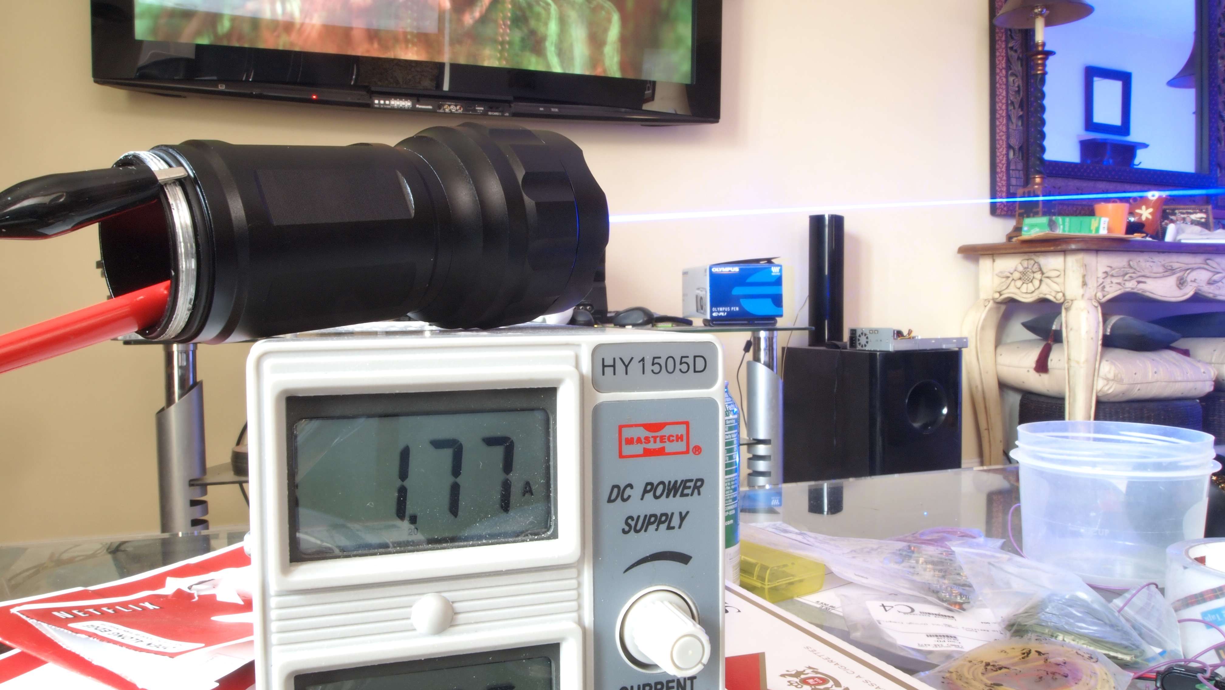
now I switched as requested, and I read between driver negative IN and the
bateries negative tab 1.5A, but only 6.46 at the batteries,
so I guess the crappy DMM in series drops ~0.33V.:undecided:

So as far as I understand, at this moment the drivers dropout is at most 2.0V
Lemme see how this goes on as the batteries run down.

EDIT:
OK, Now batteries are at 6.67 or (6.36 when measuring current) and current still around 1.48A.
Funny thing I notice, like before I noticed a drop in the diode Vf with warmup,
now I'm reading current slowly increasing with warmup, I suppose beacause of the 1085.
There were a lot of temperature related curves in it's Datasheet.:thinking:

After some 3~4 minutes, it gets so hot you can't stand to put your fingers on the heatsink for more than 4 seconds.
Mmmyeah, that tiny heatsink is not enough. It's getting boring having to make pauses.
Mind you, it's not thermally shutdown, I am chickening out instead.

OK now for example, as Vb ran down from 6.44 to 6.33, amps increased from 1.37 to 1.46.
Something to keep in mind maybe, never set this IC so it delivers a diode's MAX current when it's cold,
cause when it warms up, it might to much for the diode!!11!eleven.


Ok I think I reached a point where the party is soon to be over.
At 6.36V (with DMM in series) under load, I don't get much more than 1.40A.
So each battery has about 3.3V under load. I shoulda done this with a 3rd DMM, but I am missing the 3rd pair of probes.

EDIT:
Yep, batteries under load 6.50V (without current DMM) so 3.25V each and only getting 1.35A now.
Amperage is decreasing considerably with voltage now, so I'm guessing this is about where it goes downhill fast.
My batteries are pretty crappy too, being from an old and tired laptop pack.

1.25 A from 6.3V in.

I'm calling this a WIN for 445nm diodes and 2x LiIOn.:):)
The batteries are almost empty (3.65V each under no load), and the laser still burns the crap out of stuff.
 
Last edited:

rhd

0
Joined
Dec 7, 2010
Messages
8,475
Points
0
Will you test the drain a bit further?

But everything looks good from my seat - yes / no ?
 

anselm

0
Joined
Nov 22, 2010
Messages
2,448
Points
0
Some pictures. Don't laugh please.
gedc0705.jpg

gedc0703.jpg

gedc0706.jpg

I'm done with this test, I budged the Resistor-cloud and one contact detached
from the IC, bad solder joint to begin with apparently.

In any case, this IC has earned it's place in my labby, screw that silly LM317.:na:
 

rhd

0
Joined
Dec 7, 2010
Messages
8,475
Points
0
I just put an LM1084 (5A instead of 3A in the 1085, but otherwise the same) through a murder run. This was ~16 minute duty cycle - absolutely unintelligent length of time to run a laser for.

Although the power certainly dropped from the peak of 1,697, it did so gradually without any instability from the driver. I'd never run a laser for almost 16 minute straight like this in the real world. So I'm struggling to find a use-case that the 1085 can't tackle. I stopped the test at ~16 minutes because the heat on the outside of the host was clearly higher than you'd ever run a laser to the point of in the real-world. It was *hot* to the point of ouch-production.

Murder.gif
 
Joined
Dec 6, 2008
Messages
1,581
Points
63
I know that two #18650 "low IR" cells with LM1085 driver will drive a LD @ 1.5 amps easily.

The low IR limits the voltage drop of the 18650 cells.

The driver drop will be the 1.24 VDC + 0.9 VDC at operating temp,
for a total of ~2.1 VDC.

Larry
 

rhd

0
Joined
Dec 7, 2010
Messages
8,475
Points
0
Larry - am I right in my initial assessment that we'll never get a drop from a linear reg with 1.25V reference that is LOWER than the 1.25V reference? (and in reality, will always have to be a bit above since every IC will drop some voltage internally)

I mean that seems like a no brainer. The current reg circuit works on the principal of keeping the drop between two pins at 1.25 - so we'll always have to drop at least that much.

- I'm going to be testing an IC with a 0.4 drop, for around 1.6 total dropout in a final circuit. Implication is that 4.6 Vf + 1.6 driver drop = 6.2V (in other words, below what 2x lithium ion cells would drop to before needing to be charged anyway)
 
Joined
Jan 14, 2011
Messages
3,816
Points
63
I've decided that, at this point, I just need to start getting flexdrives, etc. Because I am using so many parts on samples to make LDO current regulators that it's a waste =p I think the LM317 design will always be limited to two-cell builds, to be honest.
 

rhd

0
Joined
Dec 7, 2010
Messages
8,475
Points
0
I think the LM317 design will always be limited to two-cell builds, to be honest.

Lol, there's no doubt about that ;)

I mean, even if there was zero dropout from some magical IC, there wouldn't be enough voltage in less than two cells.
 
Joined
Jan 14, 2011
Messages
3,816
Points
63
Well, for an LOC build. My ideal IC would be one capable of driving an LOC at 400mA or so for about 15 minutes on a single cell.
 
Joined
Dec 6, 2008
Messages
1,581
Points
63
Larry - am I right in my initial assessment that we'll never get a drop from a linear reg with 1.25V reference that is LOWER than the 1.25V reference? (and in reality, will always have to be a bit above since every IC will drop some voltage internally)

There are several linear regulators with very low dropout voltage.

If you operate in a voltage mode, which I do on some of my red builds,

you can operate one #18650 cell.

Also, my 445 build uses no driver at all.

LarryDFW
 

rhd

0
Joined
Dec 7, 2010
Messages
8,475
Points
0
Now I'm intrigued - I thought the lasing threshold of a 445 was below the maximum voltage (when fully charged) of an 18650 ?
 
Joined
Dec 6, 2008
Messages
1,581
Points
63
Larry how does that work, low voltage drop in voltage regulating mode?
I would like to power a LOC with a single LiIon!;)

First, make sure the diode has an ample heatsink.

Then, set the "Low Dropout Regulator" voltage ~3 VDC,
and check the current drawn by the Red LD.

The LM1085 will drop about 0.8VDC under 300ma load @ operating temp.

Other regulators have much less voltage drop.

You want to set it slightly under the operating current you desire,

since it will increase a few percent as it reaches the final operating temp.

LarryDFW
 
Last edited:


Top