Kenom
0
- Joined
- May 4, 2007
- Messages
- 5,628
- Points
- 63


Follow along with the video below to see how to install our site as a web app on your home screen.
Note: This feature may not be available in some browsers.


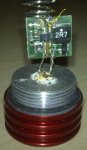
rog8811 said:Is that the way it is on the lavadrive?spring soldered to the positive side of the driver
If so I am totaly confused...does the track I have marked come from the spring? if so it goes to the case of the LD and, according to rob, is linked to the neg pin......
Regards rog8811
I see what you are saying ken, I think one of the other pictures shows the blob on the LD pin joins round the back of the leg from the driver....The driver does not appear to be reversed although it does look as though the positive pin is not connected but is instead soldered to the base of the diode.
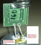
drlava said:The input capacitor on your driver appears to have been desoldered and is missing. It will not work without it. Let me know if you can't find the cap I can mail you a replacement.
(see attached)
drlava said:The input capacitor on your driver appears to have been desoldered and is missing. It will not work without it. Let me know if you can't find the cap I can mail you a replacement.
(see attached)
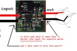
daguin said:Yes. [highlight]**IF** the case of the laser is used as the negative pathway,[/highlight] then the negative lead on the "input" side does not need to be connected. This is the case in the Kryton builds, the Dorcy builds, the leadlight builds, and many of the other laser-conversion type builds. The ground through the flexdrive is continuous.
Peace,
dave
all right thank you, i just wasnt sure...MilanTheOne said:[quote author=daguin link=1233513111/20#25 date=1233601668]Yes. [highlight]**IF** the case of the laser is used as the negative pathway,[/highlight] then the negative lead on the "input" side does not need to be connected. This is the case in the Kryton builds, the Dorcy builds, the leadlight builds, and many of the other laser-conversion type builds. The ground through the flexdrive is continuous.
Peace,
dave
all right thank you, i just wasnt sure...daguin said:[quote author=MilanTheOne link=1233513111/20#26 date=1233601875][quote author=daguin link=1233513111/20#25 date=1233601668]Yes. [highlight]**IF** the case of the laser is used as the negative pathway,[/highlight] then the negative lead on the "input" side does not need to be connected. This is the case in the Kryton builds, the Dorcy builds, the leadlight builds, and many of the other laser-conversion type builds. The ground through the flexdrive is continuous.
Peace,
dave