diachi
0
- Joined
- Feb 22, 2008
- Messages
- 9,700
- Points
- 113
A little update on the project.
When time was available this summer I tried to fight the aberration.
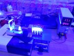
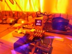
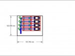
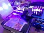
Thinking that this aberration of external beams was the result of higher refraction angles with Optlasers/Bob lenses which have pretty short f (designed for short setups) and high curvature, for my experiments I purchased some cylindricals from Thorlabs, among them ones with f = 75mm and -12.7mm, so 6x expansion could be done with lens separation twice longer than on previous pictures (pic. 1).
I suggested that longer lens separation and lower curvatures would also mean lower refraction angles of beams and reduce aberration to some extent.
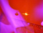
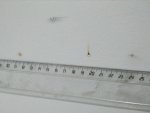
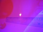
Well, the spot at 2m (500 mA) became a little (1-2mm) shorter than on setups I had before and paper sheet was igniting at 1A now and not at 1.2A like before (pic. 2). But this change was not drastic – a little more concentrated focus but still not square.
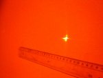
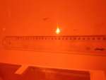
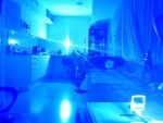
Now at 5m (here 1A current, pic. 3): it is clear to see that highly refracted out of center beams focuse closer than internal beams (sketch on pic.7). Here I show what the spots look like if the wall would be at different distances. Sorry for awkward hand righting.
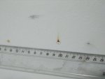
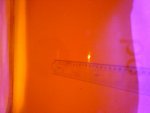
Pic. 4 shows all 4 spots when they separate again after focus range (beam waist range).
On pic. 5 two internal spots focus and combine pretty well (on line marked f 2,3 on the sketch) but two external beams are already diverging after their focus line (marked as f 1,4 on the sketch).
On pic. 6 you can see the shortest combined spot of 4 all beams if the wall is between f 2,3 and f 1,4 lines. Spot dimensions ~10x5mm.
Another thought I had was that the beams may not be perfectly parallel, if so – this could be a reason for combining beams so badly alternative to aberration.
Indeed the micro size of all Lasertack mirror mounts makes it really tricky to align properly what may be not an issue at 2m distance, but comes into action at 5m+... But from what I know aberration must lead exactly to what I see here – outer beams focusing closer than internal beams!
Do you agree?
Nice results! Aberrations are one of the tradeoffs you make with cylindrical lenses vs anamorphic prism pairs, although you can achieve higher magnification with a cylindrical lens pair. Alignment is far more touchy with the cylindrical lens pair.
Next thing I'd try is a regular Keplerian telescope (even 1x) using spherical optics and a spatial filter after your corrective optics, that should clean up some of the noise and result in improved divergence/beam quality. Hell with 4 NUBM44s you can probably punch your own spatial filter in a razor blade rather than buying ready made spatial filters.
Last edited:


")