Welcome to Laser Pointer Forums - discuss green laser pointers, blue laser pointers, and all types of lasers

Buy Site Supporter Role (remove some ads) | LPF Donations

Links below open in new window

FrozenGate by Avery

Homemade Scanning Laser Color Projector/TV

step by step diy video projector
step1: Syc separator
 

Attachments

  • P1070366.JPG
    P1070366.JPG
    102.1 KB · Views: 2,485


step by step diy video projector
step2: TEST1


Before going to play with the video signal:
 

Attachments

  • test 1.JPG
    test 1.JPG
    94.9 KB · Views: 846
  • 3.jpg
    3.jpg
    11.6 KB · Views: 556
Last edited:
step by step diy video projector
step3:
Modulation
 

Attachments

  • step3a.JPG
    step3a.JPG
    84 KB · Views: 478
  • step3b.JPG
    step3b.JPG
    77.8 KB · Views: 505
  • step2c.JPG
    step2c.JPG
    92.5 KB · Views: 593
really great work

How did you modulate the green laser at such high frequencies?

Is this how the scan angle varies click here

Also how did you make the scan linear
Is it like this patent i found online click here
 
QUOTE:

How did you modulate the green laser at such high frequencies?

Green laser modulation was explained in this thread.


Is this how the scan angle varies click here

Yes.

Also how did you make the scan linear
Is it like this patent i found online click here

No. We dont use any optical device. Additional optical devices require focusing.
We want to preserve all focus propery of the scanner. Actually we have not made any linear correction yet. Avatar of this thread is also not linear.
I suggest a computer program which rearranges the video. This will be an arcsine correction.
 
step by step diy video projector
step3:
Modification
 

Attachments

  • pattern.JPG
    pattern.JPG
    86.1 KB · Views: 901
  • mod. wave form.JPG
    mod. wave form.JPG
    92.2 KB · Views: 509
I was thinking about DLP's DMDs. In fact they are tiny mirrors vibrating at a fixed frequency. What do you think about using them as the fast mirror? I think it can be interesting!
Or it's only a crazy idea? :p
like this one has low resolution (we don't need it to be high as we need it only as a mirror), tilting angle of +/- 12° and a "scanning frequency" very very high, as far as 60MHz :eek:
http://focus.ti.com/paramsearch/doc...uiTemplateId=MDLP_PARMSRCH_T&paramCriteria=no

DMD chips are easy to find in china, as far as I know, and a hacker, GeoHotz, once hacked how they are driven (so you won't need TI's controllers).

What do you think about it?
 
I dont know much about those tiny vibrating structures.
what are their dimensions, reflectivity, flatness etc.?
 
I was wrong, those mirrors from DLP are way too fast to be used as a vibrating mirrors (minimum switching frequency is 40MHz...)


By the way. Let's say we have a system with a very low inertia (I calculated 4,76e-11 kg*m^2), I don't know the k (spring constant) of my system but I assume it is pretty high (by now I won't say what my setup is, just follow me in my reasoning ;) ). I can also apply a very high magnetic force to my vibrating mirror (I calculated with the aid of my university physics professor a very high angular momentum, something about 2500 N*m if I remember well). So I think I can have a very low inertia, high force setup. I think I can drive it at high frequencies with a good angle. Maybe if I can also drive it in vacuum it will be very interesting. I will thane a look about this.
So, if I can increase the frequency I can use higher resolutions. HD anyone?
As I want to use full cycles and not only half of them I have to reverse odd lines from a progressive video source. sltvm2007 made this by outputting the video with odd lines and odd frames reversed via software. As I am studying as electronic engineer I prefer to use an hardware solution :p
So I was thinking about a FPGA, as I can't find nothing simpler in order to process HD signal. The connectivity will be a DVI-D connector (single link, up to 1920*1200@60Hz with reduced blanking) and the video signal will be processed in a digital way before entering an high speed video DAC stage (ADV7125 I think). And now the most delicate part. Lasers.
138,24MHz of analog modulation is "a little bit" high XD
In order to have a frequency so high the diode has to be driven in a current fashion in its linear region. I am thinking about two fast operational amplifiers that "push-pull" the diode, giving also the possibility to add some bias to it and isolate it from the rest of the circuit. Maybe in this way I will be able to modulate diodes at such fast frequencies. Not simple at all. Maybe it will require a thermo-electric cell on the crystal of the green laser in order to make it thermally stable.

I know I'm going far away from the DIY idea, but I like this project and I want to expand it ;)

Let me see what do you think about it :)
 
--when you make the mirror very small, laser beam will be diffracted (instead of being reflected).
(Figure below).

Tex. Inst. accepts this phenomenon as an undesired fact.

http://focus.ti.com/pdfs/dlpdmd/Using_Lasers_with_DLP(r)_Technology.pdf


we can see a typical inteference pattern in the image scanned by MEMS micromirror. (Pic. below)


--You may of course use some DSP device instead of a computer.
 

Attachments

  • difac.JPG
    difac.JPG
    83.4 KB · Views: 576
  • microvision foto.GIF
    microvision foto.GIF
    45.9 KB · Views: 500
...Dimensions of the mirror in Kuntman's scanner is very large. There will be no diffraction and undesired interference. (This also means, there is no limit for the power of the incident beam.)

And...


Kuntman's scanner has an additonal advantage over micromechanical systems. Since it is hard as a brick, it is possible to mount some additonal components on the mirror. Such an application "fast scanning camere and lidar" was introuced in this forum as a separate thread:

http://laserpointerforums.com/f47/fast-scanning-camera-lidar-69383.html
 
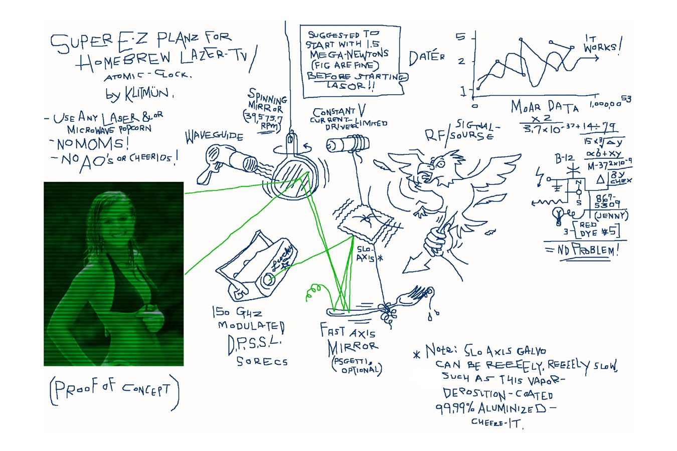
Crosspost from PL deserving of a "rofl-snort"

ItsSoEasy.jpg
 
Rofl!!

I'm pretty surprised Jon coughed up a sense of humor lol.. each and every day brings something new under the sun.
 
Last edited:
Crosspost from PL deserving of a "rofl-snort"

ItsSoEasy.jpg

Good job.
Who draw this?
It looks like a professional work!
But KUNTMAN's scanner is much faster than KUTMÜN's.
15625 Hz >> 39575 rpm. (Approx. 30 times)
 
Last edited:
Crosspost from PL deserving of a "rofl-snort"

ItsSoEasy.jpg

This is incomplete. Lacking the FLY-BACK control.
I mentioned about this to the cartoonist (on another forum: PL).
He revised his drawing.
Now it is almost complete. But it is still too slow.
 

Attachments

  • NewImproveded 1.jpg
    NewImproveded 1.jpg
    361.7 KB · Views: 290
Last edited:
Yes, dear Xer0; it is easear to buy a commercial scanner.
But the aim of this project is to explain how an amateur laserist can make his own scanner step by step without using any sophisticated pruduct.
It is a HOMEMADE SCANNING LASER COLOR PROJECTOR/TV as the title of this project says.

You have been asking the details for making this scanner for months.
Changed your mine?
Regards.
MAK

You guys are awesome for posting this stuff. As soon as my tax return comes, I'm going to build the scanners. I question electromagnet vs voice coil, however all is awesome. Modulating lasers, using raster scanning, I'm stoked. Any comments on how to determine which mosfet to use? Thanks!! Keep up the great work!

Also, where did you get your ferrite core, and why didn't you point it at the fast mirror; instead, its off to the side.
 
Last edited:


Back
Top