Welcome to Laser Pointer Forums - discuss green laser pointers, blue laser pointers, and all types of lasers

LPF Donation via Stripe | LPF Donation - Other Methods

Links below open in new window

ArcticMyst Security by Avery

Homemade Scanning Laser Color Projector/TV

Joined
Apr 28, 2009
Messages
63
Points
8
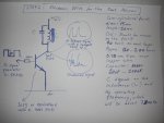
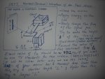
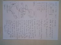
NEW FIGURE FOR TUNING THE FAST MIRROR.


Figures for the fast mirror and for high speed analog modulation of DPSS green laser.


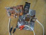
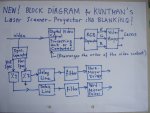
In this project, by means of two mirrors (which can be tilted about two perpendicular axis) we deflect the laser beam to scan a rectangular screen and modulate the laser source to obtain a colored image on the screen. [highlight]We don’t make use of sophisticated devices such as MEMS micromirror and acousto-optical-modulators.[/highlight]


Max. speed of the fast axis mirror is 25 KHz. That corresponds to 50000 back and fro lines per second.
In order to make use of the conventional video signal, frequency of the present scanner is tuned to 15625/2 (Hz.)

- Vibrations of both axis are resonant, therefore sinusoidal.
- Restoring force on the fast mirror is very strong and it has a very sharp resonance,
hence practically there is no phase drift;
position detectors and feedback phase control mechanisms are not required.
- Fast axis is elecromagnetically driven.
- Laser modulation is analog.

Videos:
YouTube - homemade laser projector tv (no-MEMS, no-AOM)
YouTube - laser tv (without MEMS)
 

Attachments

  • grsml.JPG
    grsml.JPG
    114.9 KB · Views: 9,767
  • rdsml.JPG
    rdsml.JPG
    144.3 KB · Views: 2,996
  • drv.JPG
    drv.JPG
    77.7 KB · Views: 4,763
  • scan.JPG
    scan.JPG
    92.8 KB · Views: 3,703
  • Kuntman's scanner2.JPG
    Kuntman's scanner2.JPG
    89.9 KB · Views: 8,998
  • Block Diagram for Kuntman's Laser  Scanner-Projector.JPG
    Block Diagram for Kuntman's Laser Scanner-Projector.JPG
    99.8 KB · Views: 8,691
  • Fast mirror.jpg
    Fast mirror.jpg
    24.9 KB · Views: 21
Last edited:


Xer0

0
Joined
Dec 2, 2008
Messages
464
Points
0
kay... and how you do it?

really, i did have this idea some months ago too. my plan was to rip off the electronics from an old tv, the part beeing used to convert composite or component input signals into a picture. and then fire it with... yes, a MEMS. dont know anything else beeing capable to scan fast enough for at least PAL...

/ps: your cam has a really weird codec! even VLC refused to play it at the first try... worked after the 3rd
 
Joined
Mar 8, 2008
Messages
2,669
Points
48
how are these 'vibrating mirrors' driven??

Are they just galvo's??


I guess I'll believe it when I see more of it... It's just hard for me to wrap my head around.  The scanning part doesn't make sense to me.

Also, as far as colors, you said the lasers were modulated by the video signal. Is this pulse width modulation (for color shades, say dark red and bright red) or is it just blanking (obviously not blanking because I see different shades of red) or is it like fading analog modulation?


Also, your resolution is only going to be as good as the beam size of your laser, unless I'm really missing something.
 
Joined
Apr 28, 2009
Messages
63
Points
8
Slow axis is resonant piezo driven
Fast axis is resonant electromagnetic driven
Laser modulation is analog.
 
Joined
Oct 10, 2007
Messages
188
Points
0
sltvm2007 said:
 
- Total cost does not exceed 10 USD.
- Low power consumption  (100mW red, green and blue lasers are enough for a picture of dimensions 100x100 cm)

How does that go together :eek:

Am i getting this wrong or something. 100mW red, 100mW blue :eek: , 100mW green for 10 USD :eek: :eek: :eek: :eek: :eek: :eek:
 
Joined
Sep 20, 2008
Messages
17,622
Points
113
Kingdingeling said:
[quote author=sltvm2007 link=1240948547/0#0 date=1240946995]  
- Total cost does not exceed 10 USD.
- Low power consumption  (100mW red, green and blue lasers are enough for a picture of dimensions 100x100 cm)

How does that go together  :eek:

Am i getting this wrong or something. 100mW red, 100mW blue  :eek: , 100mW green for 10 USD  :eek: :eek: :eek: :eek: :eek: :eek:[/quote]
A little common sense goes a long way... ::)

I'm pretty sure he is only taking about the scanning device... :cool:


Jerry
 
Joined
Apr 28, 2009
Messages
63
Points
8
Scanning part costs only few dollars.
I assume that the total cost will be considerably reduced in case of mass production.
 

diachi

0
Joined
Feb 22, 2008
Messages
9,700
Points
113
GooeyGus said:
how are these 'vibrating mirrors' driven??

Are they just galvo's??


I guess I'll believe it when I see more of it... It's just hard for me to wrap my head around.  The scanning part doesn't make sense to me.

Also, as far as colors, you said the lasers were modulated by the video signal. Is this pulse width modulation (for color shades, say dark red and bright red) or is it just blanking (obviously not blanking because I see different shades of red) or is it like fading analog modulation?

Also, your resolution is only going to be as good as the beam size of your laser, unless I'm really missing something.


I don't get it either  :-? Is it like Raster scanning, or is it scanning pictures that are TINY and then using a lens to blow them up ? I really doubt you could raster scan an image that size with HOME MADE Galvos, they would be far too slow.

Please explain this in a more simple fashion, with diagrams if possible.

-Adam


EDIT: the only way I can think of doing it is taking out the RGB cube from an LCD projector, and instead of using whitelight, splitting it up, and firing that through the LCDs on the RGB cube, you could use lasers. But if you used LCDs you wouldn't get all the lines going down the image due to the camera.

It would also be VERY difficult to get text as small as in one of your videos using lasers with "Galvos"

-Adam
 

Xer0

0
Joined
Dec 2, 2008
Messages
464
Points
0
so i did a bit research on your nice project. apparently you are searching for an investor for bringing your technology to the market. i dunno if you can find them here, this is rather a hobbyst board. but you could boost us to a new level of scanner diy building if you would share some details with us :)

ps: photonlexicon.com is a bit more dedicated to scanners etc...
 
Joined
Mar 8, 2008
Messages
2,669
Points
48
sltvm2007 said:
Slow axis is resonant piezo driven
Fast axis is resonant electromagnetic driven
Laser modulation is analog.


hmm... Still doesn't make a whole lot of sense to me. If these motors are fast enough to scan tv that well (I assume it's 'rastering' the image) then I would think that laser projectors would be using this same technology but they dont. Galvo's are still the scanning method of choice. I would think if these are that much faster that they would be more widely used.

Also, how did you get such detail in the image? Do you have to adjust the laser's focus such that it is a pinpoint on the wall? with even a 2mm or 3mm beam, which is still pretty darn good, the image would look much worse because the laser spot just isn't small enough to do fine resolution.

This is why the 'laser tv' that is part of Pangolin's software has such low resolution, because anything higher just wouldn't work.

Also with 100mW of red green and blue, your colors are going to be wacky... You need like 100mW green 200mW blue and at least 400mW 660nm red to make a halfway decent white balance. Either that or you will have to turn the green and blue dowm considerably...
 

Xer0

0
Joined
Dec 2, 2008
Messages
464
Points
0
GooeyGus said:
hmm... Still doesn't make a whole lot of sense to me. If these motors are fast enough to scan tv that well (I assume it's 'rastering' the image) then I would think that laser projectors would be using this same technology but they dont. Galvo's are still the scanning method of choice. I would think if these are that much faster that they would be more widely used.

Galvos are designed to scan paths like i understand, making lines, curves, circles etc. They change their speed and angle dynamically and guide the laser beam point-to-point. His solution uses mirrors with fixed scanning speed; the laser dot starts in the upper left corner of the screen and then goes from left to right, one line down, and repeats. so it should look jsut like a plain light square. Making a visible picture of it is now up to the modulation, having to vary the lasers intensity exactly in sync with the postions of the mirrors.

Just like the cathode ray in an old CRT ;)
 
Joined
Apr 28, 2009
Messages
63
Points
8
Thank you very much for your kind interest.
I am not able to upload pictures into this forum.
You may see some photos in the public profile of sltvm2007 in the forum: photonlexicon.
 

Xer0

0
Joined
Dec 2, 2008
Messages
464
Points
0
you can use abload.de to embed pictures here... or get 6 more posts ;)
 

Warske

0
Joined
Mar 10, 2009
Messages
145
Points
0
sltvm2007 said:
In order to make use of the conventional video signal, the resonant frequency of the present scanner is tuned to 15625Hz.
Therefore number scanned lines in each frame is 625. Refresh rate is 25 frames (50 fields) per second.
Vibrations of both axis are resonant, therefore sinusoidal.
Prior art for this type of thing used rotating mirrors, which worked well for linear (saw-tooth-wave) raster scanning.

Using resonance is a nice idea to keep the costs down and potentially improve reliability by eliminating rotating parts, but the problem is that it doesn't match standard saw-tooth-wave raster formats (eg: NTSC, PAL) without using a scan converter.

Without a scan converter, you can only display a small part of the standard raster image without considerable distortion.
 

Xer0

0
Joined
Dec 2, 2008
Messages
464
Points
0
Warske said:
Prior art for this type of thing used rotating mirrors, which worked well for linear (saw-tooth-wave) raster scanning.

This is the way how i will try it...
 

diachi

0
Joined
Feb 22, 2008
Messages
9,700
Points
113
Xer0 said:
[quote author=GooeyGus link=1240948547/0#10 date=1241043070]hmm... Still doesn't make a whole lot of sense to me. If these motors are fast enough to scan tv that well (I assume it's 'rastering' the image) then I would think that laser projectors would be using this same technology but they dont. Galvo's are still the scanning method of choice. I would think if these are that much faster that they would be more widely used.

Galvos are designed to scan paths like i understand, making lines, curves, circles etc. They change their speed and angle dynamically and guide the laser beam point-to-point. His solution uses mirrors with fixed scanning speed; the laser dot starts in the upper left corner of the screen and then goes from left to right, one line down, and repeats. so it should look jsut like a plain light square. Making a visible picture of it is now up to the modulation, having to vary the lasers intensity exactly in sync with the postions of the mirrors.

Just like the cathode ray in an old CRT ;)[/quote]


But that's just raster scanning, and you can't get high resolution with raster scanning, since the laser beam is 1-3mW wide usually, that's the size of your smallest pixel.

-Adam


Top