Welcome to Laser Pointer Forums - discuss green laser pointers, blue laser pointers, and all types of lasers

Buy Site Supporter Role (remove some ads) | LPF Donations

Links below open in new window

FrozenGate by Avery

FREE DIY open source BOOST driver!!! Tested & working!!

The ground will always STAY ground though, so the mosfet will always be ON.

The IC won't/shouldn't have any effect on how the mosfet is on or off. It's like, taking a mosfet, and then taking a switch, putting it in series with the mosfet, and switching the switch really really quickly. The mosfet doesn't care, and shouldn't care what happens after it, because it doesn't. There's no reason for the MOSFET to be switching on and off, because the gate is held to ground.

^ exactly. It's P-Channel mosfet. So the ground which is always ground when battery is inserted the right way.

It won't ever be switched or disconnected. The gate will always face 0V in that condition which means the mosfet is always on.

EDIT: the only thing that happens when using the mosfet is on startup for a very short period of time. There will be a voltage drop across the body diode of the mosfet.

So the Source pin will be V+ - approximately 1V with respect to circuit's ground. The gate pin is connected directly to ground so it's voltage is always 0V.

So Vgs = (Vg - Vs) = (0 - 2.7) = -2.7V. The mosfet requires Vgs to be at least -0.4V to turn on (or more negative than that).

So the mosfet will always be on.

And after the resistance between drain and source drops to almost nothing there will be no nearly no voltage drop anymore. We are looking at Rds of max 0.029Ohm.

Power Loss = I2R = ~2.8A x ~2.8A. x 0.029 = 0,227W of the mosfet (at max output of the LM3410)
 
Last edited:
Ok, I tried several interesting things. I look forward to my peer review! :D

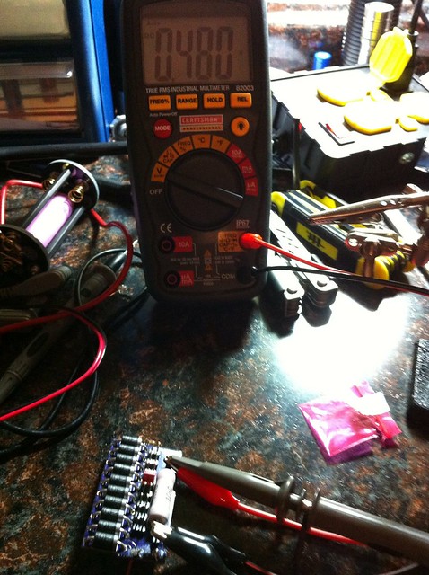
First thing I did was switch to a single 18650 at 4.3v, you can see it (pink) in the background. Did a test on the current and was getting 480mA (supposed to be 478mA so that looks good!)

I ran the voltmeter across the 1 ohm resistor and I also ran the scope across the resistor. I think you can see everything here.


Untitled by tsteele93, on Flickr

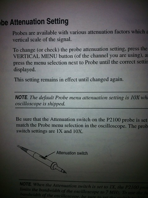
I set the Probe to 1x and the Scope to 1x. It has been at 10x on both the probe and scope for everything up to now, and I don't know if that would affect things or not. I assumed that having the scope and probe BOTH set to 10x would be correct as that is how the scope defaults and what the manual says to do.

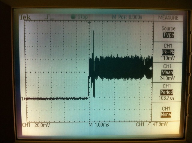
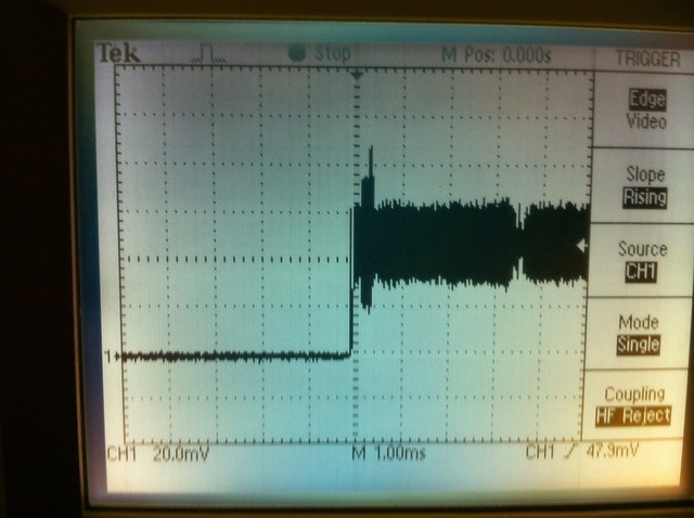
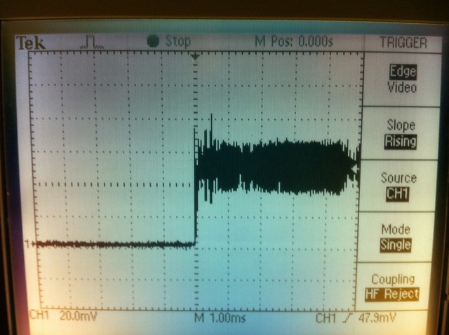
So, to be clear - the following shots were taken with the scope and probe set to 1x and the measurements taken across the 1 ohm resistor on the Jufran test load.


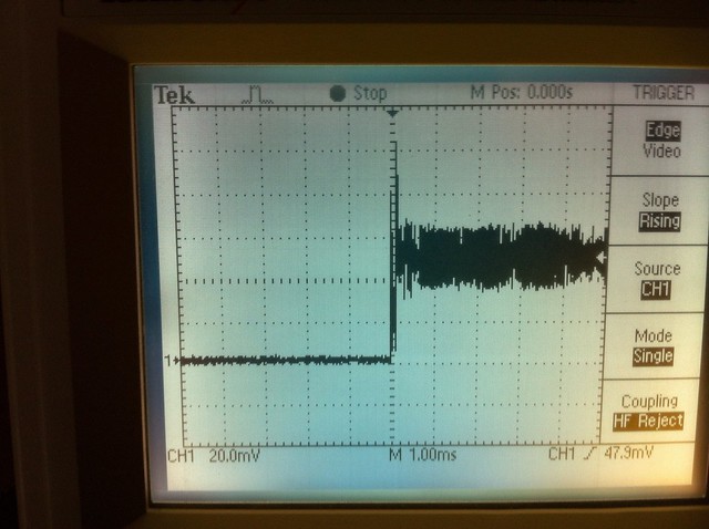
Untitled by tsteele93, on Flickr


Untitled by tsteele93, on Flickr


Untitled by tsteele93, on Flickr


Untitled by tsteele93, on Flickr

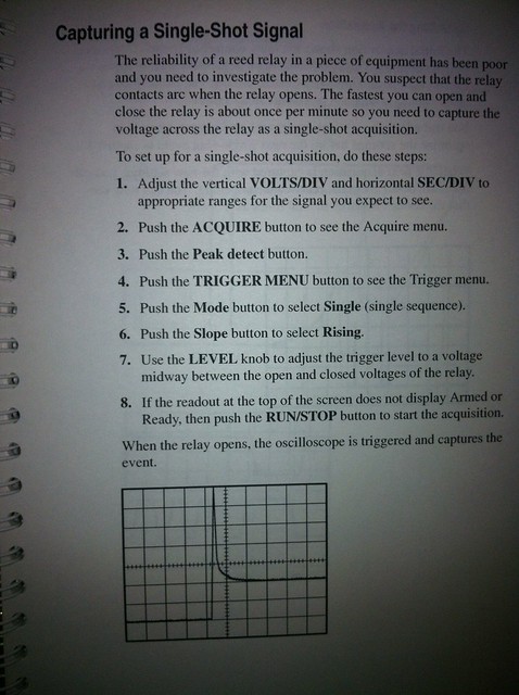
Those are all "single" traces on startup - the following shot is of the driver running.


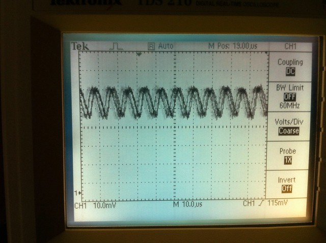
Untitled by tsteele93, on Flickr

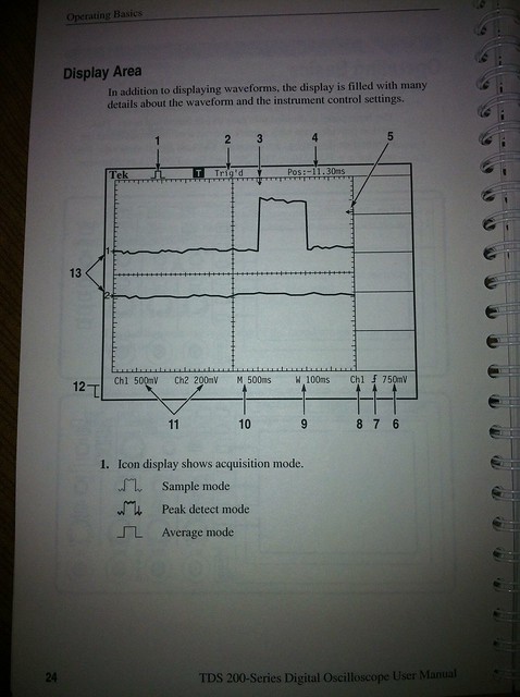
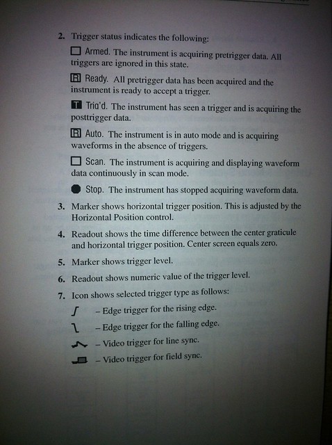
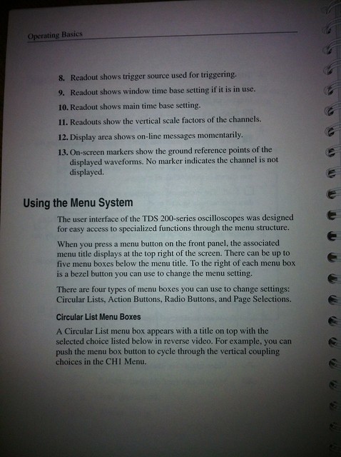
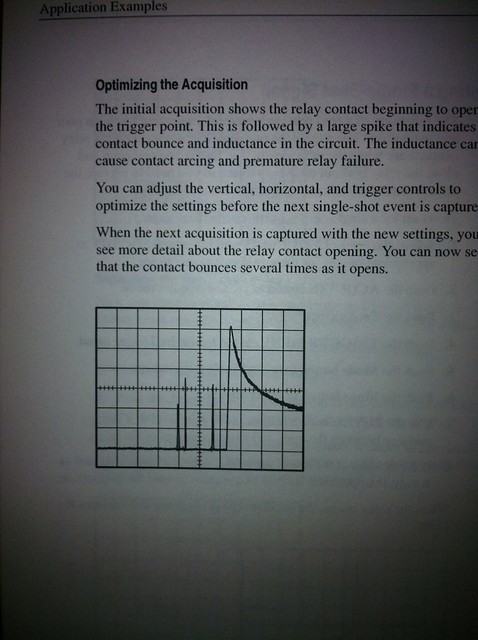
Also, here are the relevant pages from the manual...


TDS-210-24 by tsteele93, on Flickr


TDS-210-25 by tsteele93, on Flickr


TDS-210-26 by tsteele93, on Flickr


TDS-210 Single Shot by tsteele93, on Flickr


TDS-210 Single Shot 2 by tsteele93, on Flickr


TDS-210 Attenuation 10x/1x by tsteele93, on Flickr


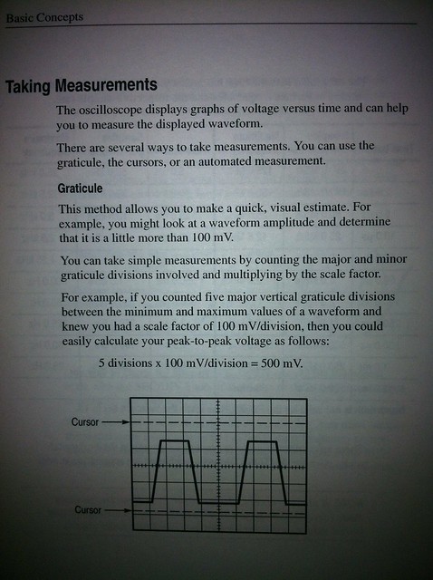
TDS-210 Measurements by tsteele93, on Flickr
 
Last edited:
So it looks like there is a LOT of ripple on the output. Looking at your second picture, the average seems good - 47.9mV corresponds to 479mA (cause you aren't in 10x, I assume - it makes sense). However, you're getting a ripple between approximately 40mV and 64mV, which corresponds to 400mA and 640mA. That, alone, is pretty bad. My guess is the output capacitor is at fault for that.

Then there is the startup spike which is pretty bad too. I would suggest decreasing the time step to see if you can actually capture it in more resolution. However, it looks like you're getting almost 90mV in spike, which would correspond to 900mA, MORE than enough to kill a 12x.

The larger capacitor may help this, but I have run into several ICs in my own driver designs that just don't like to reduce their startup-spikes, no matter the input capacitor size.

Anyway, I hope my post is useful.

EDIT: Also - you're peak-to-peak value is going to give you your maximum current that is being read for any given spike or oscillation because your minimum should be zero - i.e. there should be no reverse current flowing through your test load.
 
Last edited:
I would love to hear theories as to why the ripple would be of such a substantially lower frequency than the IC itself is operating at. Thoughts?
 
Well, it looks about 1/10th of the frequency at 1.2MHz, so it may just be the whole "10x probe" thing like it is with voltage measuring.
 
Well, it looks about 1/10th of the frequency at 1.2MHz, so it may just be the whole "10x probe" thing like it is with voltage measuring.

The frequency keeps coming out to be ~110khz, which is actually 1/15th of the of the IC's frequency.
 
Ok, I just couldn't take the suspense - and I decided to dig for my DSO Nano to do another scoping. But my soldering irons are still packed away, and so is my test load.

Solution? I had a 445 H-series with leads already soldered on, so I twirled the strands around, made a fine point, pushed it through the wirepad holes in the driver (luckily, my version of the Ben Boost still has through-holes not SMD pads for the L+/-. Then I hooked it up to my bench PSU (which was luckily already unpacked) with aligator clips. If there's ever been a setup likely to kill a diode, it was this one. The diode was un-heatsinked, wasn't properly soldered to the driver, and I did this in a carpeted utility closet, while wearing a towel (EDIT: and cotton slippers!).

The driver was set to ~540mA. I'll add for anyone watching this video: this is NOT how you should treat your diodes ;)

I did two scopings. The first was to scope the diode leads directly. That's the first video. There was a ripple of ~40mV. The DSO nano is frustrating when it comes to scaling the Y access, so I did a second scoping with a 0.1 ohm resistor in series with the diode (EDIT and scoped across the resistor leads). This allowed me to scale the Y access a bit more so that you could see the ripple in greater definition. There was a ripple of ~5mV, which given the 0.1 ohm resistance, seems in line with my first scoping.

So, assuming that TSteele did everything correctly, and that I did everything correctly, there's something up with your drivers that isn't up with mine.

Scope - YouTube


Scope - YouTube
 
Last edited:
Again; the output ripple isn't going to be sine waves.

It would be ramps. Sawtooths. What we're seeing there is high frequency (well, low frequency in the driver's case) ringing, which can be a function of any number of causes. It can be any number of frequencies too; the scope isn't reading the entire part of what's happening, so it appears to be a normal wave with no dying off.

Setting the probe to 10x won't change the way the scope reads frequency. It'll only divide the voltage by 10. 1x reads the voltage as normal.

So, the measurements he has would read out as a 90 mA spike, which isn't anywhere NEAR as bad a 900 mA spike.

Again, I'd love to test a driver out if someone would like to send me one.
 
Last edited:
Then why is it that his O-scope seemed to read 49.7mV, when his driver was outputting 497mV? o.o
 
Then why is it that his O-scope seemed to read 49.7mV, when his driver was outputting 497mV? o.o

Noob alert!

Haha, sorry Wolf, had to do that one to ya! With you, I'm 100% kidding :) But you did commit the cardinal sin.

My driver was most certainly NOT outputting 497mV. It's a boost driver, driving a 445. So it's outputting somewhere around 4.75V (the diode's Vf).

EDIT: I'll also add that the ripple I see on my scope (when I can get it expanded enough to see the shape) is a jagged saw-tooth pattern like LeQuack describes.
 
Last edited:
Eep. I meant mA! Typo. It was reading 497mV on the 1 Ohm resistor on his test load... XD

All the same, it would make sense that it would output 497mA, would it not?
 
Eep. I meant mA! Typo. It was reading 497mV on the 1 Ohm resistor on his test load... XD

All the same, it would make sense that it would output 497mA, would it not?

Oh, you're talking about his scope results?

I used a 0.1 ohm resistor, and I wasn't using it for current measurement. I use a DMM in current mode in series with the LD before scoping, just to make sure the output of the driver was correct and in line with what I had labelled it (the driver was reflowed months ago). But I took the DMM out of the equation for the scoping.


Back
Top