Welcome to Laser Pointer Forums - discuss green laser pointers, blue laser pointers, and all types of lasers

Buy Site Supporter Role (remove some ads) | LPF Donations

Links below open in new window

FrozenGate by Avery

FREE DIY open source BOOST driver!!! Tested & working!!

The mosfet isn't a part of the switching circuit though. I do see what you might be saying though, and the mosfet... well, may have problems.

If the voltage of the battery gets too low then the mosfet might not see all of the voltage it needs, and may potentially heat up/explode/smoke because it's stuck in its linear region.

And I checked up the part number on the LM3410, and it's the 1.6 mhz one. So, that's not the issue.

I don't necessarily think a low battery voltage would be an issue for this Mosfet. It has a threshold of 1V, that's pretty low.

But remember that we're sort of using it the reverse of how you'd normally conceptualize it. We're sort of counting on the current to first slip over the integrated shottky and open the gate from the other side, so to speak. Then the current would no longer flow over the shottky, and the drop between S and G would continue to keep the gate open.

What I'm saying (or suggesting / theorizing / brainstorming) is that the cycle above might keep repeating as the LM3410 goes through its cycle. It strikes me that when the LM3410 switches, it may break the input circuit long enough for the S and G differential to disappear, and the Mosfet to turn off.

Again, not a mosfet expert, but from what I understand of their theory, that's what I might expect to happen.


I don't think that's how it'd work. The gate needs -1 volt's in respect to the G-S, if I understand that correctly. If that's so, then by default the mosfet will always be on, no matter what the LM3410 is doing. Unless, of course the battery's polarity is reversed, in which case the G-S voltage would be positive, keeping the mosfet firmly off.
 
I don't think that's how it'd work. The gate needs -1 volt's in respect to the G-S, if I understand that correctly. If that's so, then by default the mosfet will always be on, no matter what the LM3410 is doing. Unless, of course the battery's polarity is reversed, in which case the G-S voltage would be positive, keeping the mosfet firmly off.

When no current is flowing across S to the LM3410, why would there be ANY voltage differential between S and G? Remember, the S is NOT connected to the battery's (+) terminal. In our usage, the S is connected to the LM3410.

attachment.php

In the second image above ^, wouldn't the Mosfet gate close if the LM3410 opened its input circuit momentarily?

I'm not arguing - you might be right. Like I said, not a Mosfet guy.
 

Attachments

  • Example.png
    Example.png
    6.8 KB · Views: 373
Last edited:
even if the LM3410 disconnects the input I don't see how that would affect anything :thinking:

even if the gate is closed it doesn't actually play any role cuz when the V+ is connected to Drain the gate is basically bypassed, no?
 
even if the LM3410 disconnects the input I don't see how that would affect anything :thinking:

even if the gate is closed it doesn't actually play any role cuz when the V+ is connected to Drain the gate is basically bypassed, no?

If what you mean is that the mosfet is bypassed by virtue of the integrated diode, then "yes sort of". That diode drops ~1V. Normally, we don't care, because the diode shouldn't be handling the current during normal operation. It's just needed at startup.

But if the LM3410 is essentially disconnecting the input and reconnecting it 1.6 million times per second, and if that does indeed cause the gate to open and close each time (or rather, try to), then you might see the input voltage into the 3410 pulsing between 2.7V and 3.7V rapidly, and/or other weird symptoms.

^ theory only. Not married to it.
 
Last edited:
I think how this MOSFET works is that having a negative voltage, relative to the input voltage, turns it on. I.e. because we have ground connected to the gate, and the positive battery contact connected to the drain, we have a negative voltage relative to the input. If the polarity were reversed, then we would have a positive voltage relative to the input, which would keep it firmly turned off.

The MOSFET doesn't care what the differential on the drain-source is, as long as it's not reversed and as long as it's not above the maximum it can handle. It just "switches on" when the gate experiences a negative voltage differential.
 
The MOSFET doesn't care what the differential on the drain-source is, as long as it's not reversed and as long as it's not above the maximum it can handle. It just "switches on" when the gate experiences a negative voltage differential.

That makes sense to me too.

So my question is - will there be a negative voltage differential between the Gate and Source if the LM3410 disconnects momentarily (like in the second diagram):
http://laserpointerforums.com/attac...ource-boost-driver-tested-working-example.png
 
Yes, there still would be, because the drain would still have a positive voltage on it and the gate zero, so there is a negative differential between the drain and the gate. At least I think that's how it works. The output of the MOSFET is irrelevant - that just dictates how much current is pulled. Whether or not it's open is all about the gate.
 
Yes, there still would be, because the drain would still have a positive voltage on it and the gate zero, so there is a negative differential between the drain and the gate. At least I think that's how it works. The output of the MOSFET is irrelevant - that just dictates how much current is pulled. Whether or not it's open is all about the gate.

Doesn't a P-Channel MOSFET turn on when there's a negative voltage between the gate and the source?
 
Last edited:
Hmm. Maybe. P and N chans always confuse me. All I know is that the "output" of the MOSFET never depends on the output. That wouldn't make any sense. It's all about the gate.
 
Hmm. Maybe. P and N chans always confuse me. All I know is that the "output" of the MOSFET never depends on the output. That wouldn't make any sense. It's all about the gate.

I'm pretty certain that a P-Channel MOSFET turns on when there's a negative voltage between the gate and the source.
 
Well, even if the circuit does break 1.6 million times a second, it doesn't mean there wouldn't be a potential there, does it? I mean, there can be no current flowing and still be a voltage. And that's really what it is - not that the voltage goes to zero.
 
the circuit breaks but that doesn't mean that the input is totally disconnected!

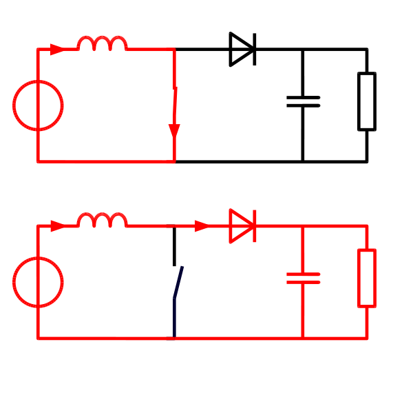
when the internal switch is opened current continues to flow through the inductor,diode,cap and load from the input (which means the input is still connected)

when the switch is closed the current is built up in the inductor.

so what we see is the input is always connected. it doesn't cut off.

boost.png
 
Last edited:
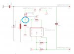
I would still be really interested to see a scoping of the point highlighted by the circle:
attachment.php


Given that the voltage differential relative to GND at that point in the circuit is crucial to the Mosfet staying open, I'd like to know that there are no issuex introduced by the IC that complicate this.
 

Attachments

  • Point.png
    Point.png
    20.7 KB · Views: 321


Back
Top