- Joined
- Dec 27, 2011
- Messages
- 2,062
- Points
- 48
Ok, I will be uploading in a few. I was able to successfully remove the caps and put on new ones and plug it up and get .480 amps again. But the scope readings seem quite different. Let me upload.
UPDATE: Here is what I did...
First, I re-scoped the original driver to make sure I had a baseline to work from and then I tried to re-create the exact same thing after I had removed the 10uF caps and replaced them with the 22uF caps.
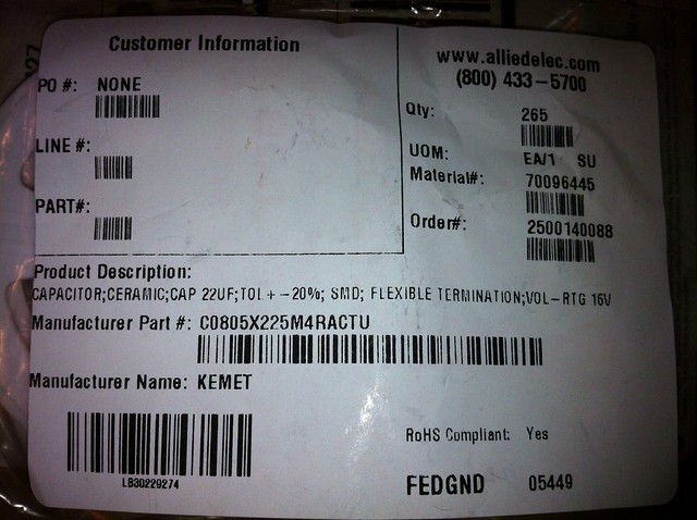
EDIT: THESE CAPACITORS WERE INCORRECTLY LABELED! THEY ARE ACTUALLY 2.2uF CAPACITORS, WHICH TOTALLY CHANGES A GREAT DEAL ABOUT THIS TEST. ALLIED ELECTRONICS HAD THEM LISTED WRONG IN THEIR CATALOG. So I look like a dummy, I have a hundred dollars worth of capacitors that are wrong by a factor of 10 and have even sent these out to some people to use in their drivers. Even stranger, they seem to work ok?!?
So... Please consider that any caps labeled as 22uF in this thread are actually 2.2uF!
Untitled by tsteele93, on Flickr
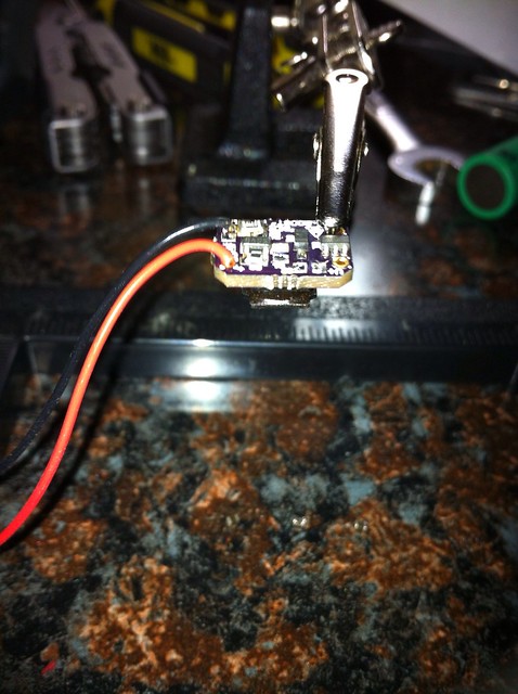
I used a heat gun to remove the 10uF capacitors and then put the 22uF caps in place and used the heat gun to replace them. It went surprisingly smoothly.
Untitled by tsteele93, on Flickr
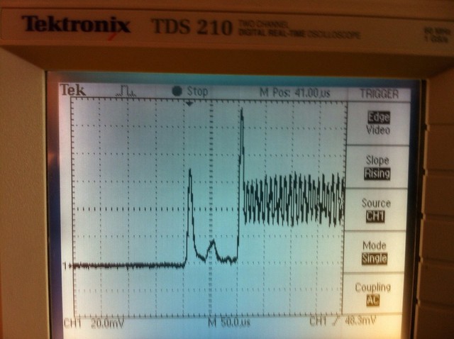
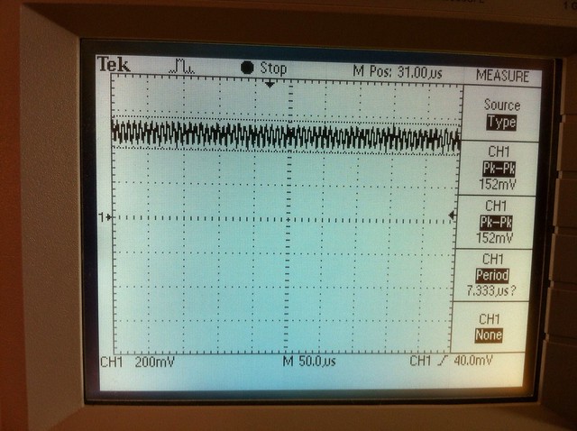
Foulmist asked me to try scoping in AC mode so I started with that. I followed the instructions using the PEAK mode and got this with the 10uF capacitors.
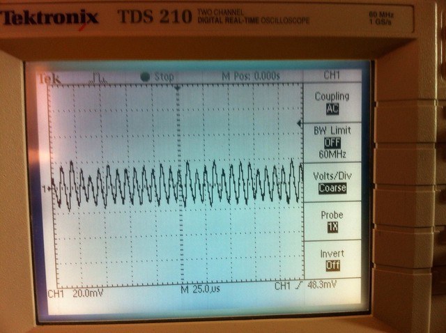
1x probe, 478mA driver, 10uF caps, AC, running by tsteele93, on Flickr
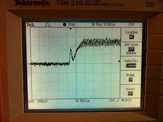
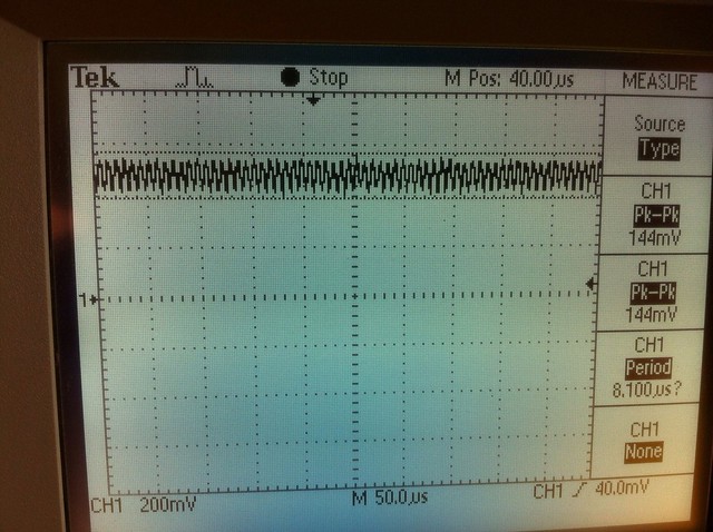
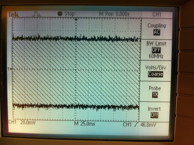
The same reading with 22uF capacitors resulted in a completely different looking waveform.
Untitled by tsteele93, on Flickr
I even tried it using SAMPLE MODE instead of PEAK MODE to see what was going on.
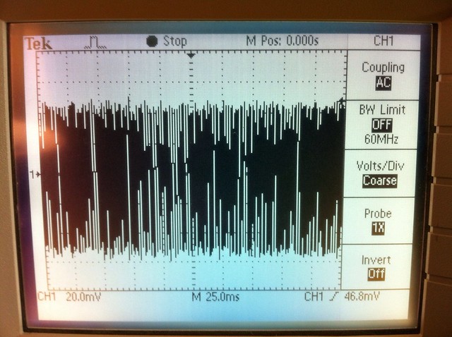
Untitled by tsteele93, on Flickr
Keep in mind though, these are with 1x on the probe and that seems to limit the scope to a 7Mhz max and could result in incorrect readings.
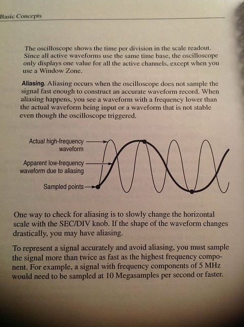
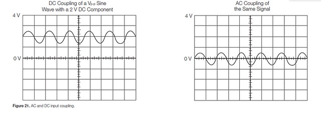
Oscilloscope Aliasing by tsteele93, on Flickr

Aliasing Frequencies by tsteele93, on Flickr
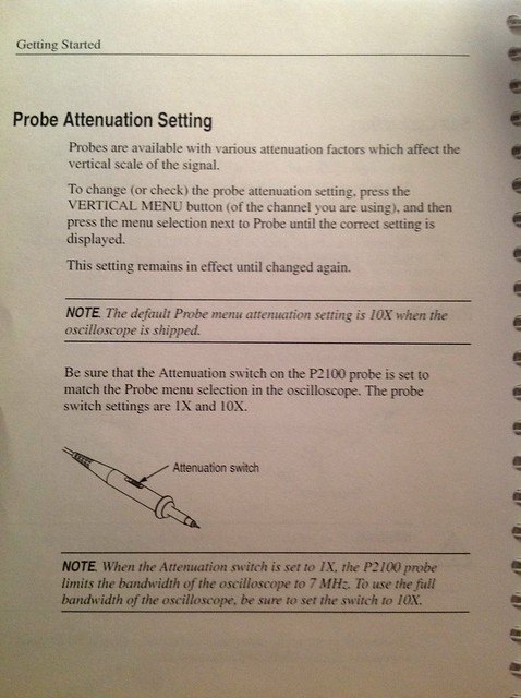
Probe Attenuation by tsteele93, on Flickr
So I did the same thing with the scope and probe set to 10x...
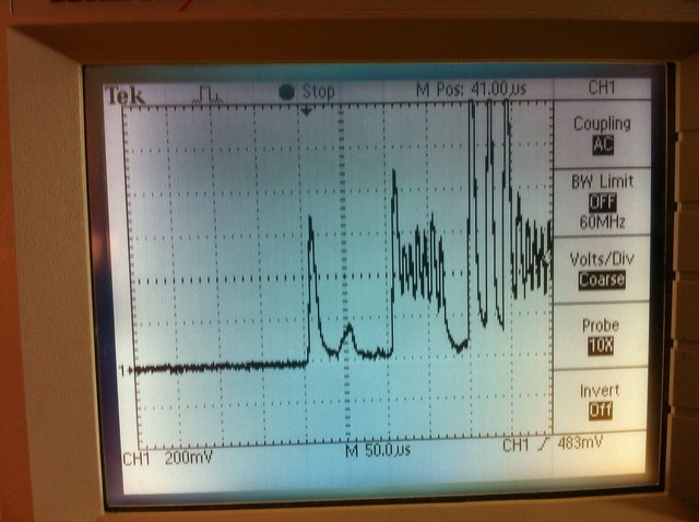
Here is the running AC waveform with the 10uF capacitor:
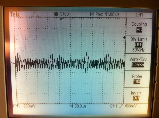
Untitled by tsteele93, on Flickr
And here is the running AC waveform with the 22uF capacitor:
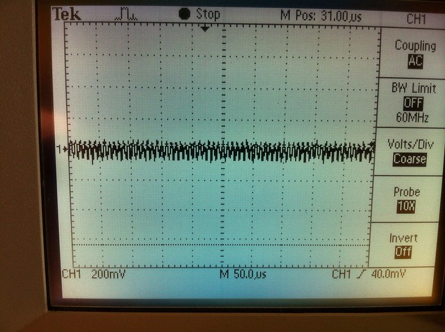
Untitled by tsteele93, on Flickr
Next I looked at the same scenario with DC instead of AC.
Here is the 10uF capacitor with a 1x probe:
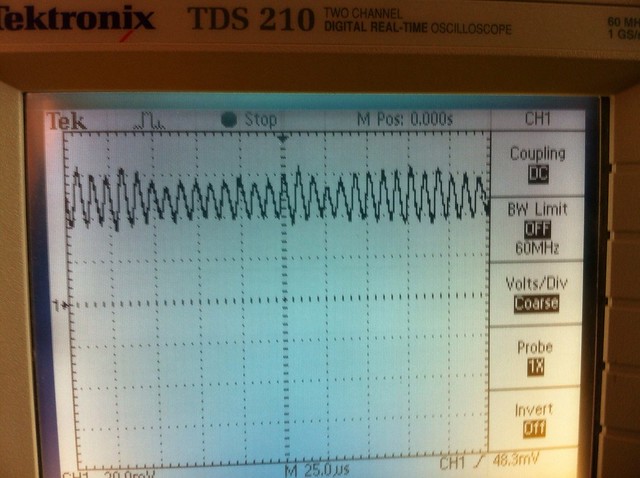
1x probe, 478mA driver, 10uF caps, DC, running by tsteele93, on Flickr
And here is the 22uF capacitor with the 1x probe:

1x Probe, 478mA, 22uF, DC, running by tsteele93, on Flickr
Now the same two waveforms with the 10x probe, so the first one is the DC waveform with the 10x probe and 10uF capacitor:
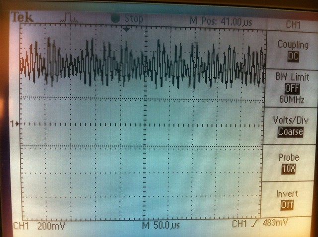
10x probe, 478mA driver, 10uF caps, DC, running by tsteele93, on Flickr
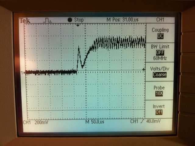
And now the DC waveform with 10x probe and 22uF capacitor:
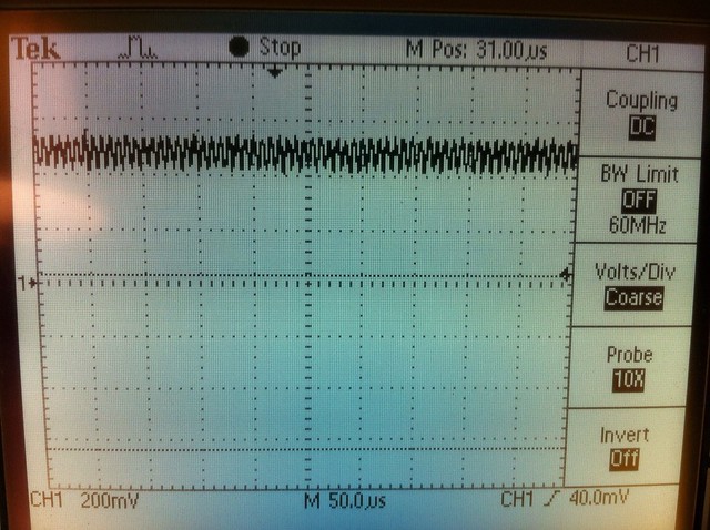
10x Probe, 478mA, 22uF, DC, running by tsteele93, on Flickr
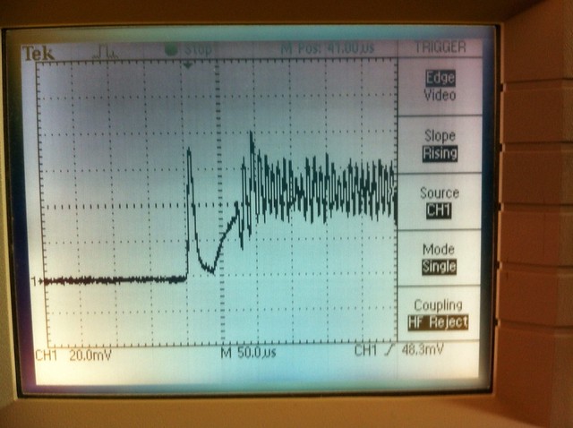
I'm going to post this and then add some more captures of startup spikes next.
UPDATE: Here is what I did...
First, I re-scoped the original driver to make sure I had a baseline to work from and then I tried to re-create the exact same thing after I had removed the 10uF caps and replaced them with the 22uF caps.
EDIT: THESE CAPACITORS WERE INCORRECTLY LABELED! THEY ARE ACTUALLY 2.2uF CAPACITORS, WHICH TOTALLY CHANGES A GREAT DEAL ABOUT THIS TEST. ALLIED ELECTRONICS HAD THEM LISTED WRONG IN THEIR CATALOG. So I look like a dummy, I have a hundred dollars worth of capacitors that are wrong by a factor of 10 and have even sent these out to some people to use in their drivers. Even stranger, they seem to work ok?!?
So... Please consider that any caps labeled as 22uF in this thread are actually 2.2uF!

Untitled by tsteele93, on Flickr
I used a heat gun to remove the 10uF capacitors and then put the 22uF caps in place and used the heat gun to replace them. It went surprisingly smoothly.

Untitled by tsteele93, on Flickr
Foulmist asked me to try scoping in AC mode so I started with that. I followed the instructions using the PEAK mode and got this with the 10uF capacitors.

1x probe, 478mA driver, 10uF caps, AC, running by tsteele93, on Flickr
The same reading with 22uF capacitors resulted in a completely different looking waveform.

Untitled by tsteele93, on Flickr
I even tried it using SAMPLE MODE instead of PEAK MODE to see what was going on.

Untitled by tsteele93, on Flickr
Keep in mind though, these are with 1x on the probe and that seems to limit the scope to a 7Mhz max and could result in incorrect readings.

Oscilloscope Aliasing by tsteele93, on Flickr

Aliasing Frequencies by tsteele93, on Flickr

Probe Attenuation by tsteele93, on Flickr
So I did the same thing with the scope and probe set to 10x...
Here is the running AC waveform with the 10uF capacitor:

Untitled by tsteele93, on Flickr
And here is the running AC waveform with the 22uF capacitor:

Untitled by tsteele93, on Flickr
Next I looked at the same scenario with DC instead of AC.
Here is the 10uF capacitor with a 1x probe:

1x probe, 478mA driver, 10uF caps, DC, running by tsteele93, on Flickr
And here is the 22uF capacitor with the 1x probe:

1x Probe, 478mA, 22uF, DC, running by tsteele93, on Flickr
Now the same two waveforms with the 10x probe, so the first one is the DC waveform with the 10x probe and 10uF capacitor:

10x probe, 478mA driver, 10uF caps, DC, running by tsteele93, on Flickr
And now the DC waveform with 10x probe and 22uF capacitor:

10x Probe, 478mA, 22uF, DC, running by tsteele93, on Flickr
I'm going to post this and then add some more captures of startup spikes next.
Last edited:


