hello,
i'm finally building this tool.
i use the same display of Kalmito (0V t0 33V 5 digits) tested with my multimer, works good, event with milliV. from 0 to 4.5V, it has 4 digits after the decimal point, if voltage is greater than 4.5V is has 3 digits after the decimal point.
two input, one for the display power (VCC and GND connected to the power supply), the other used to check voltage.
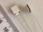
and the same TEC Klamito use, the Laird ot18,18,FLA 0608.
looking at the image attached, cathode should be the left wire, anode the right.
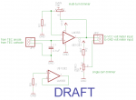
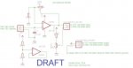
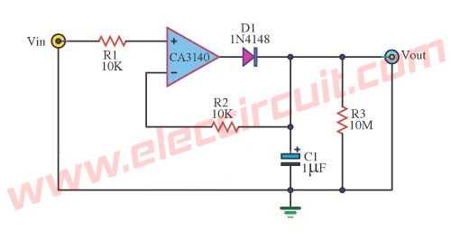
i'm using schematics as attached.
all test where double checked on connections.
i've 2 problems:
1) TEC connection
wired as the schematics, display is fixed at 0.0018V, no change to display, also tried with other tec, results is always the same.
to make something works i've to swap TEC connections, heating the TEC, makes voltage change.
2) zero pot
the zero pot does not make any change to my display.
thanks for your help.


")