Welcome to Laser Pointer Forums - discuss green laser pointers, blue laser pointers, and all types of lasers

Buy Site Supporter Role (remove some ads) | LPF Donations

Links below open in new window

FrozenGate by Avery

DIY Thermal LPM for under $50

The Isis offers peak detection when data logging.

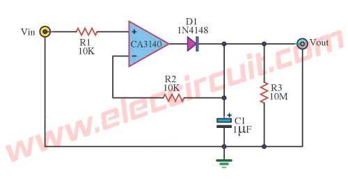
You could use that peak detector circuit, just remember to add the voltage drop of the diode to your final output :p
Or you could make a digital LPM.


The Isis offers peak detection when data logging.

You could use that peak detector circuit, just remember to add the voltage drop of the diode to your final output :p
Or you could make a digital LPM.

It also doesn't register anything below 200mW, unless you placed it on a negative rail. And even then you'd need something that could read the negative voltages.
 
The Isis offers peak detection when data logging.

You could use that peak detector circuit, just remember to add the voltage drop of the diode to your final output :p
Or you could make a digital LPM.

In January I will buy Isis! 1000000% :P

digital LPM is not my area!I dont have schematic! :(
 
Unfortunately this circuit will not work well for this application. The use of the diode D1 will cause a 0.6v drop for silicon diodes, ~0.2v for schottky diodes which means the output of the opamp will be 200mW to 600mW lower than the true peak detected on the input.

Agree. There is a better circuit in the link for this with no diode on the input side.

precision-peak-voltage-detector-with-a-long-memory-time.jpg
 
what do you use to fix (paste / glue) the peltier to the heat sink?
 
Last edited:
You can just use those cheap thermal adhesive from eBay or you can also use something like the Arctic Silver thermal epoxy.
 
You can also mix some aluminium powder with regular epoxy if you're in a pinch.
 
hello,
i'm finally building this tool.

i use the same display of Kalmito (0V t0 33V 5 digits) tested with my multimer, works good, event with milliV. from 0 to 4.5V, it has 4 digits after the decimal point, if voltage is greater than 4.5V is has 3 digits after the decimal point.
two input, one for the display power (VCC and GND connected to the power supply), the other used to check voltage.

and the same TEC Klamito use, the Laird ot18,18,FLA 0608.
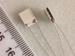
looking at the image attached, cathode should be the left wire, anode the right.

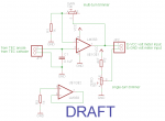
i'm using schematics as attached.
all test where double checked on connections.

i've 2 problems:

1) TEC connection
wired as the schematics, display is fixed at 0.0018V, no change to display, also tried with other tec, results is always the same.
to make something works i've to swap TEC connections, heating the TEC, makes voltage change.

2) zero pot
the zero pot does not make any change to my display.

thanks for your help.
 

Attachments

  • $(KGrHqR,!nQE8Yt8y!m7BPO43gfHBg~~60_35.JPG
    $(KGrHqR,!nQE8Yt8y!m7BPO43gfHBg~~60_35.JPG
    13.6 KB · Views: 197
  • lpm_mariomaster_lasermeter.png
    lpm_mariomaster_lasermeter.png
    8.7 KB · Views: 251
1) TEC connection
wired as the schematics, display is fixed at 0.0018V, no change to display, also tried with other tec, results is always the same.
to make something works i've to swap TEC connections, heating the TEC, makes voltage change.

2) zero pot
the zero pot does not make any change to my display.

Try a powering the amp with a +/- voltage and make the pot go from -v to +v.

You may have to mess around with the zeroing resistance values a bit.

Sent from my phone. Sorry for any spelling errors.
 
hello,
i'm finally building this tool.

i use the same display of Kalmito (0V t0 33V 5 digits) tested with my multimer, works good, event with milliV. from 0 to 4.5V, it has 4 digits after the decimal point, if voltage is greater than 4.5V is has 3 digits after the decimal point.
two input, one for the display power (VCC and GND connected to the power supply), the other used to check voltage.

and the same TEC Klamito use, the Laird ot18,18,FLA 0608.
looking at the image attached, cathode should be the left wire, anode the right.

i'm using schematics as attached.
all test where double checked on connections.

i've 2 problems:

1) TEC connection
wired as the schematics, display is fixed at 0.0018V, no change to display, also tried with other tec, results is always the same.
to make something works i've to swap TEC connections, heating the TEC, makes voltage change.

2) zero pot
the zero pot does not make any change to my display.

thanks for your help.

I use other connection!
954038195easylpm2_www.kepfeltoltes.hu_.jpg


The IC 5pin connect with 1K to "+" :)
 
@ARG
tryed your solution, no luck, i've always my two problems.

@Kalmito
tryed, no luck.

my zero pot just does not work.
@Kalmito:
1) does your zero pot make the display goes to 0.0000?
2) looking at the TEC from the above, like the picture i previously sent, is the right wire of your TEC connected to pin 3, and left wire connected to GND?

1)
My zero pot is work, but I connected the
display impulz cable to V.M out +,
display - (gnd) connected to V.M. out -
display + cable to 9V
and zero pot to maximum!
and you have 0.000 :)

2)
Irrelevant to the TEC which is pin connect, because the only difference that must be heated or cooled, which half! But for me it is the way you wrote it.

Sorry fot the bad english! :)
 
This circuit's zeroing only works if the meter has a separate power source than the signal it is measuring. If you use a common ground meter the zero will not work.
 
Thank you!

Now its clear, it is the common ground missing on my display.
Doing like the attached circuit to me work.
Please tell me if i do made things wrong.

I've also put the original design reference, if it is not a problem for @MarioMaster.
 

Attachments

  • lpm_mariomaster_lasermeter.jpg
    lpm_mariomaster_lasermeter.jpg
    27 KB · Views: 199


Back
Top