Welcome to Laser Pointer Forums - discuss green laser pointers, blue laser pointers, and all types of lasers

Buy Site Supporter Role (remove some ads) | LPF Donations

Links below open in new window

FrozenGate by Avery

DIY Homemade laser diode driver

Status
Not open for further replies.
@Rad86N, that calculation is correct... but only shows you the power consumed by the LD. Most of that is converted into heat. Only about 20-25% are emitted as laser light.

@oldscooliron, LDs (or LEDs in general) are current-driven, not voltage-driven - you set a certain current on the driver and don't worry about the voltage. I'm not sure which diode the 20x is - I know that the common drive current for the red LOC LPC-815 is ~420mA and for the bluray PHR-803T it's ~120mA (less for longer life).

I=U/R so min resistance means max current and vice versa.


thanks "dr-ebert" for that info!

I finally found someone saying a 20x dvd burner LD they think was being run at 400ma. Does this sound right? I take it I can just set the current to 250ma & be safe then?

Is it necessary to use a heatsink & fan other then the AixiZ Laser Module?

Can someone tell me if I'm right? I'm using a red colored laser so I would buy blue or dark green glasses then?

If I'm going to make a 250ma laser I would need more then OD3+ glasses?
 
Last edited:
Can someone tell me what these numbers mean?

With my driver (25 ohm pot) set at "max." (meaning the least risistance) using the "test load" & placing the DVM leads on the 1 ohm resistor the DVM reads ".285" on "min." it reads "48.3".

My DVM is set on "DC v"

My voltage is 1.26 at the resistor & regulator so I know that's good.
 
Last edited:
Now this is the way to make your first post ! +1 cudos dude and Welcome to the forum...

Best Regards Pyro... :eg:

Hey Guys
I'm new to the forum, but have been experimenting with this circuit for about 6 months now. I needed to run a phr 803t on 6 volts in a MXDL host . The LM317 has a voltage drop of 2.25 volts which makes it unsuitable for my application, so I set out to find a similar chip regulator that would work. I found the ST Microelectronics LD1117V which is a Low DROPOUT version of the LM317. It only drops out one volt instead of 2.25 volts. Mouser Electronics has these in the large TO220 case and the small DPAK and SOT223 cases. Last time I checked the price at Mouser was about 40 cents apiece. The circuit hooks up exactly the same way as the LM317. The LD1117V allowed me to run my phr on two CR123 lithium primarys. I hope this info will be usefull to anyone who needs it.
It worked for me. regards DIYer

@ oldscooliron sounds like you have your vom set to ohms you want it set on milivolts each milivolt = one miliamp also since you basicly have no idea what you are doing it would be a good idea to NOT turn things all the way to the max [(25 ohm pot) set to "max"], electronic parts can only be streched to there limits for short periods of time, be cautious ! or spend more money !

Best Regards Pyro... :eg:
 
Last edited:
@DIYer:

you misunderstood something wrt the LD1117V regulator. The 1V dropout applies to a constant voltage output setup - it means if you want a 5.0V regulated output, the input can be as low as 6V. However, a driver operates in constant current mode. Here you've got a "sense resistor" in the output as well. The voltage drop over this resistor is fed into the sense input of the IC. This reference voltage is 1.20V typ. for the LD1117V and 1.25V typ. for the LM317 - the total voltage drop in constant current mode is thus ~2.3V for the LD1117V while for the LM317, it's ~3.0V (meaning it's comfortably higher than usually told around here).

@oldscooliron: I also can't make head or tails of your numbers...
 
I have the DVM set on DC volts.

When you say "max" you mean min. resistance which gives the most power correct?

I know it may sound like I don't know what I'm doing but I do have some know how with electronics (not alot but some) my point being I know how to test for shorts, read AC/DC voltage, polarity but when it comes to reading the numbers on a circuit that's where I get confused.

Here is a picture of where I'm getting the numbers.

 
Last edited:
Is your meter auto ranging?
With that resistor setup you should get a max of 250ma and a min of 41ma, so your numbers come out close just the decimal point seems wrong.


Regards rog8811
 
Last edited:
Yes, that seems likely: you'd get the 200mV range of the DMM for the low current (it would show about 45mV) and the 2V range for the high current (0.250V display).

So everything looks ok, except that your DMM seems to read about 10% high - the 4 diodes should have a bit below 3V as well. Still, it's within expected tolerance limits. Maybe you can compare your meter against a reference voltage, e.g. a Zener diode or a known high quality DMM.
 
@ rog8811 yes

I forgot to mention I'm using 6 AA's @ 7.5v maybe that's where the differences is?

I re-tested everything & here's what I get: (I noted if it volts or mV on max or min) (Max pot turned all the way to the left. Min pot turned all the way to the right)


The following are pics of (max resistance pot turned all to left)


Last edited:
Can someone tell if I'm right here? I'm a machinist & I figure math is math so I think I should be right.

1000mV = 1 Volt

500mV = .500 Volts

250mV = .250 Volts

100mV = .100 Volts

50mV = .050 Volts

If .283V (max "pot turned all to left") lights up my LED very dull & 45.2mV lights it up bright (min. "pot turned all to right") there is more juice flowing to the LED @ 45.2mV because there is less resistance. 45.2mV is much less then 250mV which is 250ma. So if that 45.2mV is the least resistance (with the pot turned all the way to the right) the circuit can't allow anymore current to go through because it's at the very least resistance it can be at how can you reach 250mV? What am I missing here?


The long leg on caps, & LEDs is + right? If so I know my polarity is correct. Resistors have no polarity & diodes only let the current flow in one direction (and + is connected to the silver side of the diode) right?
 
Last edited:
The conversion factor 1V=1000mV is correct. However, your use of "max" and "min" seems to be mixed up. You'll get maximum current (.283V = 283mA) if the pot has minimum resistance - depending on how you've connected it, that may be with the pot turned all the way left or right, no way to tell from here. The pot should have 3 pins. You use only two: the middle one and one of the others. The 3rd one can be left unconnected, or connected to the middle one. If this 3rd one is on the right as in your circuit diagram (and assuming the rest of your circuit is laid out before you similar to the diagram as well), then having the pot turned all the way left (counter-clockwise), you'd get minimum resistance and maximum current and max brightness - so it would operate opposite to what you may expect - normally, if you turn a "dimmer" clockwise, you'd increase the brightness, while in your setup you'd decrease it.

The value you read off the DMM represents the current, or "juice". More current = more brightness.

Since you do get a reading with your test load, and your LED does light up, you know you've got the polarities correct.
 
If .283V (max "pot turned all to left") lights up my LED very dull & 45.2mV lights it up bright
The only way I could see that being the case is that you are massivly overdriving the LED at the top end, I do not know what LED you are using but I have had them dim as the current rises as they are starting to burn up.
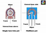
The pot to the right, in the drawing is what I assume is close to the one you are using, as drawn, with the wiper as far left as it will go, connecting to the left hand pin and the middle would give you zero resistance. Connecting to the right hand pin and the middle would give you 25ohms resistance.

Hope that helps.

Regards rog8811
 

Attachments

  • pot comp01.jpg
    pot comp01.jpg
    42.7 KB · Views: 1,591
@ dr-ebert

I have the pot wired with the middle & 3rd pin with a jumper wire together & the 3rd pin going to the circuit. If you watch "Phaznol" video that's how I did it. You can also see it in "rog881" circuit diagram it's the same way. And this is where my confusion came in.

@ rog8811

The only way I could see that being the case is that you are massivly overdriving the LED at the top end, I do not know what LED you are using but I have had them dim as the current rises as they are starting to burn up

This is where my confusion came in. I knew .283V was more then 45.2mV but could not understand why the LED was brighter @ 45.2mV now with your info I now know I had to be overdriving the LED because it did indeed burn out after a couple tries!

Thank you for all your help guys! It's much appreciated!

So just to recap here reading my DVM if it shows .125V or 283V that is 125ma or 283ma. Correct? Even though .125V & .283V is really "mV"

I just finished hooking the LD up & it works correctly now just to adjust the len but I guess I'll wait until I get some glasses before that.
 
Last edited:
Yes - because you're not measuring the current directly, you're measuring the voltage drop it causes by flowing through the resistor.
 
Hey.. I'm trying to figure out what are the best and max current and voltage for 16x and 18x and 20x dvd burner diodes.. can somebody please tell me..
I tried to search it but then searching within 10billion posts, that's just insane.

Btw im not using the 5ohm resistor between the pot and the adjust pin of the LM317T. So thats why i need those numbers.. and my power source has 5.2V. .yeah. and im using a different diode - 1N4007, for some reason my local shop doesnt have 1N4001.
 
Btw im not using the 5ohm resistor between the pot and the adjust pin of the LM317T

If you get it wrong that is over 1amp through the LD without a fixed resistor.

best and max current and voltage

This is a constant current driver so the voltage will take care of itself....but....

and my power source has 5.2V

...so only 2.5v for the laser diode?....

I tried to search it but then searching within 10billion posts, that's just insane.

This thread has a few graphs that may be of help.
http://laserpointerforums.com/f42/meta-topic-pinout-performance-actual-ld-26417.html

1N4007 should be OK, just measure the voltage drop over one of them to see that it gives you 0.7v

Regards rog8811
 
Status
Not open for further replies.


Back
Top