Welcome to Laser Pointer Forums - discuss green laser pointers, blue laser pointers, and all types of lasers

LPF Donation via Stripe | LPF Donation - Other Methods

Links below open in new window

ArcticMyst Security by Avery

Diodes Compilation - All Diodes Data In One Thread!

gillza

0
Joined
Jul 26, 2010
Messages
583
Points
28
I think at this point we need to include the data on most used Diodes (12x from lite on, 445nm A130 A140, etc) and put in the experimentally obtained data confirmed in at least 2 or 3 applications. If you will wait until official data becomes available from manufacturer this will stay the way it is now forever! It is too conservative!

Besides you can always go back and correct the values when better experimental data is available.


Joined
Jul 13, 2010
Messages
98
Points
8
I don't know if there is a rule of thumb or not when determining pinout or voltages or even current ratings for that matter for laser diodes, I just don't want to unnessesarily FRY any of my diodes if I can avoid it, and of course would like to know ahead of time what the power output of adiode is so I don't waste my time trying to get a big output from a 5mw diode, thinking it might be a 1 watt diode or something!

I hope someone out there can steer me in the right direction!
Thanks!

;)

I just use my digital multimeter's lowest resistance scale. Diodes, by deffinition, only conduct in one polarity, so some combination will have continuity of a couple of ohms or so, and the wrong ones will show open. It has a diode testin mode, too, but I don't know how that would work for a laser diode, the good old continuity test works for me. The only thing is that you have to probe all three pins to one another, in both polarities till you find the combination that has low resistance continuity (not a dead short, either). I have a driver I made out of an LM317 with a linear pot to regulate it's output. I connect to that, once I have the pins figured out, and gradually turn it up until it reaches the lasing threshoid. I can also then check the resistance across my pot, to calculate the output of the LM317, to get a ballpark figure of how much juice it draws.
That might not be the right way, but it works for me with what I have, and what I know, and it doesn't fry diodes. Here is a link to the LM317 diagram and calculator, the current control one (only one resistor, not two) is the same as every basic LM317 driver diagram, and the resistor value/output current calculator is very handy.
http://diyaudioprojects.com/Technical/Voltage-Regulator/
 
Last edited:
Joined
Aug 15, 2009
Messages
1,443
Points
48
You're digging up a year old thread to reply to a 2 year old post 2 pages back AND you give advice that blows up diodes!
NEVER connect a multimeter in ohm or diode mode to a diode! The reverse voltage it may give can kill a diode and you may discharge a cap though the diode in forward mode, so this is a method that is likely to kill diodes. Some diodes also have a photodiode to monitor the output which you also need to take into account.
Please be carefull when giving advice, others may follow it.
 
Joined
Aug 13, 2011
Messages
80
Points
0
For diodes without photodiode I use my dmm to find the right polarity, but I use the diode-tester mode. I know my meter is limited to 3v and 2mA. The meter is a cheap UNI-T UT33D. It is actually limited to the same values in resistance-mode too, but then it does, as Bluefan mention, use a cap to stabelize the values.
(I could not find a cap in the diode path though.)

It barely makes my red diodes glow dimly, and it's definately too low for lasing.

Bluefan has a good point regarding photodiodes though, as they do conduct and appear remarkably like LD's on this simple reading.

Another issue is the IR LD's in some dual packages. They seem to have a lower Vf than the RED ones but I mostly identify em by the tiny red glow from the "right" one.
 
Joined
Aug 14, 2011
Messages
1,109
Points
0
You're digging up a year old thread to reply to a 2 year old post 2 pages back AND you give advice that blows up diodes!

Someone needs to update the OP, or better yet, make a new one. This bad boy is getting long in the tooth! :D (<-- just noticed that the smiley has pretty long teeth :crackup:)
 
Last edited:
Joined
Aug 13, 2011
Messages
80
Points
0
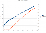
Lite-ON 50HW-16935 DVD-RW:

Wavelengt: RED
Power: ?
Lasing threshold: Approx 60 mA
Vf at lasing threshold: 2.16 V

Attached is a graph I did with diode in aixis module, fitted in 40x40x20mm cooling block with temperature-control at ambient-8°C (approx 20°C).
I didn't dare go much higher but may do so later.

My power-meter is uncalibrated so only relative measurements possible.
(Direct mV readings from a 15x15mm TEC painted matte black with forced convection sink on the back.)
 

Attachments

  • lite-on_sohw-16935_ifv-graph.png
    lite-on_sohw-16935_ifv-graph.png
    27 KB · Views: 895
Joined
Dec 27, 2011
Messages
2,062
Points
48
This thread could almost stand to be unstickied. It is not updated at all and much of the data is fading into history...
 
Joined
May 24, 2012
Messages
582
Points
28
Anyone have info on the GGW-H20L Diode?
The 405nm not the 650. Thanks
Matt
 
Last edited:
Joined
Aug 22, 2012
Messages
25
Points
1
I know this thread is old and surely that's why it's not included, but I feel like data on the PHR 805t should be included...especially considering it is replacing the PHR 803t and has a different pinout...it also seems to be many peoples first build but lots of confusion about it
 
Joined
Jan 8, 2009
Messages
3,145
Points
83
I know this thread is old and surely that's why it's not included, but I feel like data on the PHR 805t should be included...especially considering it is replacing the PHR 803t and has a different pinout...it also seems to be many peoples first build but lots of confusion about it

Used the search and this was the first hit this should be EVERYthing you need to mount that diode. http://laserpointerforums.com/f50/phr-803t-red-ir-diode-pinout-currents-36212.html
 

gillza

0
Joined
Jul 26, 2010
Messages
583
Points
28
I will risk sounding like a broken record but, I have proposed in another thread that we could create a publicly editable documents (google docs) with build summaries and diode information (specs, current, voltage, output etc)

http://laserpointerforums.com/f44/diodes-specs-build-compilation-threads-77027.html

Anyone would be able to edit the info in them. In addition there are backups available in case some one messes the content up.
 
Last edited:
Joined
Aug 22, 2012
Messages
25
Points
1
Used the search and this was the first hit this should be EVERYthing you need to mount that diode. http://laserpointerforums.com/f50/phr-803t-red-ir-diode-pinout-currents-36212.html

Forgive me in I'm a complete noob but I'm pretty sure that thread has nothing to do with a PHR 805t diode...in fact it says 803t right in the thread and shows some funky 4 pin diode which has IR also...

is the PHR 805t brand new or something? Whenever I ask about it I seem to be skirted off by people and sent to info about the PHR 803t...
 
Joined
Jan 8, 2009
Messages
3,145
Points
83
Forgive me in I'm a complete noob but I'm pretty sure that thread has nothing to do with a PHR 805t diode...in fact it says 803t right in the thread and shows some funky 4 pin diode which has IR also...

is the PHR 805t brand new or something? Whenever I ask about it I seem to be skirted off by people and sent to info about the PHR 803t...

No YOUR RIGHT... that's not the intended thread I apologize. Here is the right thread http://laserpointerforums.com/f38/phr-805-405nm-diodes-replace-phr-803ts-62591.html and props to cliff on that. Post #6 is where the meat is on the pin on that diode best I can tell. I'm in and out today sorry for the confusion.:eek:


Top