Welcome to Laser Pointer Forums - discuss green laser pointers, blue laser pointers, and all types of lasers

LPF Donation via Stripe | LPF Donation - Other Methods

Links below open in new window

ArcticMyst Security by Avery

BIG capacitor bank

vk2fro

0
Joined
Nov 30, 2009
Messages
1,304
Points
63
I did take your suggestion about the bolts tho for the caps - just ordered 10 x M6x10mm bolts. If they dont fit, I've lost $5, if they do, I'll order another 30 to complete the 5kJ version :)

Also found my old tool box, and inside, 6,7, and 8mm hss drill bits so thats one less thing to buy. :)
 
Last edited:


Joined
Nov 22, 2010
Messages
239
Points
28
I managed to launch a hockey ball 200 feet in the air with my cap bank :)

No details yet...
 

vk2fro

0
Joined
Nov 30, 2009
Messages
1,304
Points
63
A hockey ball is quite a heavy object (about the weight of a full soda can). Nice work :)
 

vk2fro

0
Joined
Nov 30, 2009
Messages
1,304
Points
63
I reckon I can put this thing battery and all into a road case with wheels. Will make for easy transportation, and if I hide the output behind one of the removable panels, no one can contact it. Use slidable rack drawers for easy service and maitenence. What do you guys reckon?

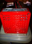
Edit: Federal Signal Divisions 450D 24VDC horn just rocked up :)

attachment.php


Looks like it means business. Once I can get some long suitable cables, I'll put it at one end of the apartment and test it from batteries at the other end of the apartment. I am not testing a 100dB horn at point blank range (apparently these things are loud :p). Its a brand new horn too :)

Built a timer module to pulse the horn at 1 second bursts 1 second relax, for 3 bursts. This means you can simply press the alarm button, and the circuit does the rest. Alternativly, I can wire it to the firing arm switch so it locks out the fire button until 3 bursts have sounded. :)

Pressing the alarm button while the mode selector is in "charge position" simply acts as a test button for the horn, bypassing the timer and lockout module; which when in bypass mode, completly powers down the trigger board. When ever the fire mode is selected, the strobe will flash.

edit: progress! I hit jaycar today!

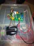
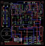
I have wound the step up transformer (what a pain that was), completed the inverter board (and removed one bug, so yes it has a bodge wire on the back, and a cut trace!), calibrated the cutoff trimpots (9v = 25mv 90V= 250mv, 900V = 2.5V), and built a poor mans fast bridge out of UF4007 diodes.

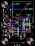
I also designed the interlock pcb and the timer/trigger pcb. Really the timer and trigger can go on veroboard, its all low voltage crap, and I might just do that to save myself some money.

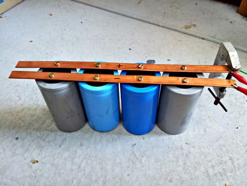
Now just need to get some bolts and wire up 2 capacitors in series and see if the inverter works.

The transformer - ugly as sin, but you try winding 400 turns of fairly fine wire without breaking it :p

attachment.php


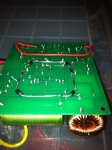
The bodgey wire (tm) and the poor mans fast bridge below it
attachment.php


and without this pic I wouldnt have noticed the error - one of my diodes is backward in the bridge. Thats not gonna work too well ;)
 

Attachments

  • IMG_0046.JPG
    IMG_0046.JPG
    52.4 KB · Views: 573
  • IMG_0047.JPG
    IMG_0047.JPG
    56.4 KB · Views: 638
  • IMG_0048.JPG
    IMG_0048.JPG
    53.8 KB · Views: 562
Last edited:

vk2fro

0
Joined
Nov 30, 2009
Messages
1,304
Points
63
ok guys just ordered an analogue meter for the bank box, a huge stud diode for back emf quenching, and the correct meter for the control box. Oh, and PCB's for version 5.

The original pcb worked about 3 times then 3 traces blew off :p Too much current (I hadn't made them wide enough).

The new version has the transformer on board (not based on a flyback core), along with the HV bridge. It also incorporated a 555 to shut down the charger for 10 seconds once target voltage is reached, to prevent the circuit from oscillating as the voltage fluctuates above and below the target voltage. It is also adjustable from 50V right up to 1200, so I can make a second one, pop a 12position rotary switch and bam! I have a cap reformer.

I have also designed the trigger board, and its being made as well. A simple circuit too. Both board have complete isolation via relays - all the user is switching is the coil current.

So this project is now waiting on parts. In the mean time I'll build the bank itself from the bolts, bus bars, socket set and centre punch I have, and set it aside until the new boards arrive.

attachment.php


and the trigger board:
attachment.php


if you spot the tiny trace near the zener diode on the trigger board, thats an oversight, and an offcut off a resistor will be used to beef up that trace. The trigger is all low current crap anyway, but better to be safe than sorry :)

if these all work properly (they should, I've spent the last week going over it all!), I might sell them as kits w/prewound transformer. (many electronics enthusiasts get confused winding transformers, or simply cant be stuffed!). It will make life easier for someone to experiment with capacitors. (of course I wont sell prebuilt modules, you assemble it and shock yourself with it, you're to blame. I assemble it and you shock yourself, well, litigation anyone?) :p
 

Attachments

  • trigger.jpg
    trigger.jpg
    61.6 KB · Views: 740
  • capchargerv5.jpg
    capchargerv5.jpg
    46.7 KB · Views: 929
Last edited:
Joined
Nov 8, 2010
Messages
25
Points
1
I’d be in for one of these kits if you where to sell them, atm I’m using a very crude method to charge the caps(mot with a 27V transformer feeding it for a 300v charge)

Heres the cap bank as it is, looks like I got the same as you have vk2fro

2011-12-08_18-54-24_HDR.jpg


Only charged it to 150v so far and that was loud enough at the time.
 

vk2fro

0
Joined
Nov 30, 2009
Messages
1,304
Points
63
darn - no multiquote on this forum!

coldice, you seem to have the goods, arent they loud? I charged up 4 of mine (series parallel) and it made quite a loud crack. Got 3 shots and on the 4th, during charging 3 traces blew off the pcb LOL

HIMNL9, stop poo pooing my thread with your big capacitor banks. Either send me one of those or quit showing off (just kidding mate) :D (oh and I thought my 2.5kJ bank was pretty powerful. 50MJ?? hmmm ok 200ft remote lead!)
 
Last edited:

HIMNL9

0
Joined
May 26, 2009
Messages
5,318
Points
0
LOL :p ..... ok, i send one to you ..... do you have a room big enough for store it ? (ehm, and the 10 million Euro it cost, ofcourse ..... :D)

BTW, multiquotes works, for me ;) ..... but as alternative, you can use an old trick, if on your PC it does not work ..... just click the quote button for each post you want to quote keeping the "CTRL" key pressed (this will open each quote in a new tag, in FF, probably also in IE), then you can just copy/paste each quoted text in a single window with your own replies, and close all the other ones, posting them in a single post.
 

vk2fro

0
Joined
Nov 30, 2009
Messages
1,304
Points
63
Thanks for the heads up himnl9 I'll keep that idea in mind. Now as for the capacitors; your shout :)

edit: bloody ipad auto spell check, and edit 2 - multiquote appears on the PC, but not on the ipad for some reason.

edit 3: finally got bolts that fit the caps, my centrepunch, a socket set to do up the SCR clamp (always needed one of these around the house anyway - have you seen the size of some of the bolts on 1/5th scale RC's), and some relays and a 12-24v step-up conveter to power the contactor and 24v alarm.
 
Last edited:
Joined
Feb 11, 2008
Messages
730
Points
0
I find microwave oven diodes to be the best diodes to use for pulse power HV projects. I would go for series parallel config for 1400V. Due to the high transient amperage and ringing, I'd use a spark gap switch with a little argon/co2 mig gas as the dielectric since the device is moderate high voltage very high current. A triggered spark gap switch is easy to build, reliable, and the trigger coil must be tied capacitively to both main electrodes to prevent what happened to your transformer.
 

vk2fro

0
Joined
Nov 30, 2009
Messages
1,304
Points
63
My setup will now disconnect the charging system from the bank when the rotary selector switch is moved from charge to fire. The firing system cannot enable if the switch is in the charge position. A big 400A contactor handles this. Makes a solid "thump" when it makes or breaks :)

Trigger element is a 1200 volt SCR (I wont exceed 900V), with a pulse rating of some 17,000 amps.

Microwave diodes arent fast enough, hence the use of the UF4007 fast diodes. This circuit switches in the 100s of khz range so microwave diodes would not recover quickly enough.
 

vk2fro

0
Joined
Nov 30, 2009
Messages
1,304
Points
63
Well trust me to get a dud battery drill. Went to use it to drill my bus bars, and it wouldn't go after I'd charged the battery. OF course it was an ODTGTO brand, so once pulled apart, you will never get it back together, despite trying with all sorts of tools and ideas. Once the hydraulic press shattered the case, I gave up. Frigging cheap chinese shit. OF course my next battery drill will probably be a makita or a dewalt!

GRRR! :(

Looking on the bright side, I now have a spare 14.4 v battery to charge thumper (the no longer drills battery) along with a gearbox and OWWIWT trigger switch, which will be the first target for thumper to destroy. (only works when it wants to). The fault appeared to lay in the direction switch, which once removed from the hand tool, was never designed to go back in.

Time for a smoke; before I grab said battery drill parts and throw them through a window (preferably open. Broken drill is enough, broken window = more money LOL)
 
Last edited:

LaZeRz

0
Joined
Feb 19, 2011
Messages
2,549
Points
63
Well trust me to get a dud battery drill. Went to use it to drill my bus bars, and it wouldn't go after I'd charged the battery. OF course it was an ODTGTO brand, so once pulled apart, you will never get it back together, despite trying with all sorts of tools and ideas. Once the hydraulic press shattered the case, I gave up. Frigging cheap chinese shit. OF course my next battery drill will probably be a makita or a dewalt!

GRRR! :(

Looking on the bright side, I now have a spare 14.4 v battery to charge thumper (the no longer drills battery) along with a gearbox and OWWIWT trigger switch, which will be the first target for thumper to destroy. (only works when it wants to). The fault appeared to lay in the direction switch, which once removed from the hand tool, was never designed to go back in.

Time for a smoke; before I grab said battery drill parts and throw them through a window (preferably open. Broken drill is enough, broken window = more money LOL)

Meh, battery drills are shit. Get a 1050watt hammer drill like me :)


Top