
Welcome to Laser Pointer Forums - discuss green laser pointers, blue laser pointers, and all types of lasers
How to Register on LPF | LPF Donations

Navigation
Install the app
How to install the app on iOS
Follow along with the video below to see how to install our site as a web app on your home screen.
Note: This feature may not be available in some browsers.
More options
You are using an out of date browser. It may not display this or other websites correctly.
You should upgrade or use an alternative browser.
You should upgrade or use an alternative browser.
BIG capacitor bank
- Thread starter vk2fro
- Start date


vk2fro
0
- Joined
- Nov 30, 2009
- Messages
- 1,305
- Points
- 63
Even with mine I'd be betting it would last about 5 or 6 shots then the contacts would be toast. Unless it has an insane peak power rating.
piferal
0
- Joined
- Apr 5, 2011
- Messages
- 1,161
- Points
- 0
Maybe you need a vacuum contactors.
Here you have some powerful examples.
Vacuum Contactors 3TL7 - Siemens
Power Apparatus & Components | Components | Vacuum Contactors | HCV-/1JBU/1KAU
CG Vacuum Contactor ( Power Quality Solutions )
Here you have some powerful examples.
Vacuum Contactors 3TL7 - Siemens
Power Apparatus & Components | Components | Vacuum Contactors | HCV-/1JBU/1KAU
CG Vacuum Contactor ( Power Quality Solutions )
Last edited:
Trevor
0
- Joined
- Jul 17, 2009
- Messages
- 4,386
- Points
- 113
Have you considered using the Geek Group's method - just allowing a short arc?
-Trevor
-Trevor
vk2fro
0
- Joined
- Nov 30, 2009
- Messages
- 1,305
- Points
- 63
I've thought of that - I'd figured out a contraption using a rat trap, a polyurethane block and some copper.
Then Centrx came to the rescue with a rather inexpensive clamp ($39.99 plus shipping) so I said yes to the quotation.
Considering some surplus places sell the puck scr alone for well over $100 getting the clamp and the puck for under $100 is a bargain if your like me and your metal working skills run out at drilling holes in a uniform pattern along a bus bar.
I'm also happy to pay someone else to make the clamp, if its going to cost me a bunch in new tools to do it. As it is, the tool budget is just going to cover a new drill press in a couple of weeks (I'm going to need one, as soon as the bank is made, I'll be getting some lasers together and finishing Thor.)
So now I just need to make a schematic for a firing board (schmitt trigger, gate driver + transformer) and I'll be all set.
edit: my pcb's have arrived")
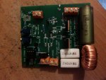
Heres one I made earlier.

Some observant people may notice that some parts are not installed. The diodes leads are too big! I will buy some UL4007F diodes to replace these, which have a slightly smaller lead.
I also need to buy a 110K resistor and 5K trimpot for the meter section, along with a switch. Then I can get to testing.
As for the slightly skewif screw terminals on the bottom, this was an oversight on my part. It wont affect the operation, just looks darn ugly.
Then Centrx came to the rescue with a rather inexpensive clamp ($39.99 plus shipping) so I said yes to the quotation.
Considering some surplus places sell the puck scr alone for well over $100 getting the clamp and the puck for under $100 is a bargain if your like me and your metal working skills run out at drilling holes in a uniform pattern along a bus bar.
I'm also happy to pay someone else to make the clamp, if its going to cost me a bunch in new tools to do it. As it is, the tool budget is just going to cover a new drill press in a couple of weeks (I'm going to need one, as soon as the bank is made, I'll be getting some lasers together and finishing Thor.)
So now I just need to make a schematic for a firing board (schmitt trigger, gate driver + transformer) and I'll be all set.
edit: my pcb's have arrived
Heres one I made earlier.
Some observant people may notice that some parts are not installed. The diodes leads are too big! I will buy some UL4007F diodes to replace these, which have a slightly smaller lead.
I also need to buy a 110K resistor and 5K trimpot for the meter section, along with a switch. Then I can get to testing.
As for the slightly skewif screw terminals on the bottom, this was an oversight on my part. It wont affect the operation, just looks darn ugly.
Attachments
Last edited:
vk2fro
0
- Joined
- Nov 30, 2009
- Messages
- 1,305
- Points
- 63
Still working on this folks, its been put aside as funds must go to fix my laptop. I dropped it and it needs a new screen. Ebay to the rescue, I'll have it back up and running in a few days.
Then its time to organise the plexiglass enclosure, a bigger sloping panel box (the switches are huge!), and a few other bits!

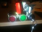
Going clockwise from top to bottom left:
1: Arming switch for firing button
2: Mode selection switch. Dump / Charge / Fire
3. Interlock - stops people messing with bank. I need a second one for the bank box.
4. Charging switch. Lights up green when the selector switch is in "charge" setting.
5. Firing switch. Lights up red when selector switch is in "fire" setting, and SW1 is cover open and toggled up.
Still needed: Another red switch (ALARM!). Sounds an alert that the bank is about to fire. ALA Geek Group style.
Another Green switch (Dump). Manual dumping switch that drops a 10K 300w resistor across the bank for a slow bleed, in case I overcharge. This would be used in situations where I want 1000 volts, and accidentally charge to 1100V. Drops the bank below 100V in 5 minutes if held down.
Another Red switch: (E-Dump): Drops a 2K 500W resistor across the bank for a fast emergency discharge. Should drop the bank below 100v in around 30 seconds.
The 10K 300 W resistor is placed online when the selector is set to dump. The strobe lamp will continue to flash and no way of disconnecting power to it until the the bank drops below 10v. If the control console is unplugged, the bank box will continue to flash its strobe, and start sounding the alarm at 1 second intervals until the control box is plugged back in, or until the bank drops below 10V. This saftey feature is to remind you to monitor the bank at all times, even if you are not going to use it. Use of the slower discharge resistor was decided because this is less stressful on the caps.
Lid of bank will lock shut automatically via solenoid once voltage is above 10V.
Then its time to organise the plexiglass enclosure, a bigger sloping panel box (the switches are huge!), and a few other bits!
Going clockwise from top to bottom left:
1: Arming switch for firing button
2: Mode selection switch. Dump / Charge / Fire
3. Interlock - stops people messing with bank. I need a second one for the bank box.
4. Charging switch. Lights up green when the selector switch is in "charge" setting.
5. Firing switch. Lights up red when selector switch is in "fire" setting, and SW1 is cover open and toggled up.
Still needed: Another red switch (ALARM!). Sounds an alert that the bank is about to fire. ALA Geek Group style.
Another Green switch (Dump). Manual dumping switch that drops a 10K 300w resistor across the bank for a slow bleed, in case I overcharge. This would be used in situations where I want 1000 volts, and accidentally charge to 1100V. Drops the bank below 100V in 5 minutes if held down.
Another Red switch: (E-Dump): Drops a 2K 500W resistor across the bank for a fast emergency discharge. Should drop the bank below 100v in around 30 seconds.
The 10K 300 W resistor is placed online when the selector is set to dump. The strobe lamp will continue to flash and no way of disconnecting power to it until the the bank drops below 10v. If the control console is unplugged, the bank box will continue to flash its strobe, and start sounding the alarm at 1 second intervals until the control box is plugged back in, or until the bank drops below 10V. This saftey feature is to remind you to monitor the bank at all times, even if you are not going to use it. Use of the slower discharge resistor was decided because this is less stressful on the caps.
Lid of bank will lock shut automatically via solenoid once voltage is above 10V.
Attachments
Last edited:
vk2fro
0
- Joined
- Nov 30, 2009
- Messages
- 1,305
- Points
- 63
Finally - thanks to a good friend I have 2 CRT TV's to gut for their LOPT transformers.
I also have a mot i can rip the secondary out of for the secondary windings on the transformer. The primary I'll just use cable from an dead ham radios power lead.
The next step is to get the bigger control console box, the copper bus bar and the plexi to make the enclosure for the bank.
Then its just a matter of forming my caps (they've sat idle for months), and wiring them in the series parallel strings. For the forming process, I might make a second charger and control it from a basic stamp (i have one spare) with an LCD, which will ramp the voltage up sequentually in 25V steps and hold that voltage for 15 minutes. This pretty much automates the process and will allow me to put the forming machine and capacitor outside, should the cap decide to change its properties and become a hand grenade
I should have my SCR clamp in a few days.
I laughed at the huge aluminium clad wirewound resistor I got off ebay for the purpose of dumping the charge if I'm not going to fire... - its the size of a sausage roll
Last edited:
Bluefan
0
- Joined
- Aug 15, 2009
- Messages
- 1,443
- Points
- 48
Why not take microwave transfomers? Easily 1000W at 3kV.
Don't forget that the power resistors probably need good heatsinking.
Don't forget that the power resistors probably need good heatsinking.
vk2fro
0
- Joined
- Nov 30, 2009
- Messages
- 1,305
- Points
- 63
The microwave transformers work great when their primaries are fed 240VAC (mains is 240 here).
They tend to not work very well when fed 12VDC.
I have some nice heatsinks out of the guts of a dead 12V linear power supply. They should do the job.
edit: Clamp just arrived - this thing looks cool - gotta get a socket set to assemble it. I'll take a photo later once I get off the phone
They tend to not work very well when fed 12VDC.
I have some nice heatsinks out of the guts of a dead 12V linear power supply. They should do the job.
edit: Clamp just arrived - this thing looks cool - gotta get a socket set to assemble it. I'll take a photo later once I get off the phone
Last edited:
vk2fro
0
- Joined
- Nov 30, 2009
- Messages
- 1,305
- Points
- 63
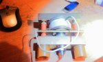
heres a photo of the SCR clamp.

its not "clamped" yet as I dont have my bus bars. I should have them in a few weeks when more money comes in for the project. Once I have them the project can begin to move along quite quickly
edit: bored this morning, I picked up one of my flybacks. It was surprisingly easy - but a tad tedious to wiggle out the core - the stubborn bit was the bottom half, which required a bit of coaxing with some zippo fluid to weaken the glue (which seemed like a poor version of hot glue) and then with the aid of a aaa rechargeable battery (just the right size to slip down into the guts of the transformer, it popped right out without damage. So if you want an easy to get at FBT core, pick a CHEAP chinese telly - they go sparingly with weak glue
I made sure to reassemble the core with the little spacers, which are imperitive to its operation. It now sits with the banks parts. I'll get some screws tomorrow for the caps, and the copper will be ordered on thursday for the terminals.
But very soon, I'll be able to test the charging circuit, as today I'll be picking up 8 1A 1Kv fast diode to complete the inverter Coilform will be 3m OHP transparency for the secondary. It will be placed on a wooden dowel the same diameter as the core, then I'll wind on as many turns that will fit, add another layer of 3m transparancy, and continue until I have approximatly 450 turns. Then I'll heatshrink it, and slip the transformer core through it.
its not "clamped" yet as I dont have my bus bars. I should have them in a few weeks when more money comes in for the project. Once I have them the project can begin to move along quite quickly
edit: bored this morning, I picked up one of my flybacks. It was surprisingly easy - but a tad tedious to wiggle out the core - the stubborn bit was the bottom half, which required a bit of coaxing with some zippo fluid to weaken the glue (which seemed like a poor version of hot glue) and then with the aid of a aaa rechargeable battery (just the right size to slip down into the guts of the transformer, it popped right out without damage. So if you want an easy to get at FBT core, pick a CHEAP chinese telly - they go sparingly with weak glue
I made sure to reassemble the core with the little spacers, which are imperitive to its operation. It now sits with the banks parts. I'll get some screws tomorrow for the caps, and the copper will be ordered on thursday for the terminals.
But very soon, I'll be able to test the charging circuit, as today I'll be picking up 8 1A 1Kv fast diode to complete the inverter
Coilform will be 3m OHP transparency for the secondary. It will be placed on a wooden dowel the same diameter as the core, then I'll wind on as many turns that will fit, add another layer of 3m transparancy, and continue until I have approximatly 450 turns. Then I'll heatshrink it, and slip the transformer core through it.Attachments
Last edited:
vk2fro
0
- Joined
- Nov 30, 2009
- Messages
- 1,305
- Points
- 63
Didnt make it to jaycar yesterday or today - got halfway up to the train station and started to feel yuck, so in my best interests (and not my electronics interest) I returned home. Been crook since, but at least I've been ok enough to jump on the computer and help a few fellow forum members with their projects on here
Should be right tomorrow - if I'm feeling up to going down the pub with a friend, i should be good to hit jaycar tomorrow (and mail the phone I sold on ebay - bet the poor guys is wondering if I've ripped him off or not. Hopefully he will see the email I sent apologising for my slow performance!). I'll pick up some diodes, some ECW and some test leads, along with the 110K and 5K resitor and trimpot.
Then I can sit in front of the computer with some geek group youtube clips and wind a transformer. Joy LOL
vk2fro
0
- Joined
- Nov 30, 2009
- Messages
- 1,305
- Points
- 63
Just ordered the remaining bits for the bank PCB.
I'd get 4 ultrafast diodes from jaycar for $10.
From ebay I got 50 diodes - $5.99, 300 resistors (including the value I need for $1), and a 25 turn 5k trimpot for $2 for the meter calibration. So I spent less on ebay including postage, than going to jaycar for four measly diodes. Since the project has taken this long, waiting on a little international postage isnt going to hurt.
All I need now is a stud diode for freewheel protection, a contactor for charger isolation, copper and a box
edit: just found a massive 300A 1400v puck diode on ebay cheap. Tempted!
(oh and to do the boring bit and wind the transformer).
Last edited:
vk2fro
0
- Joined
- Nov 30, 2009
- Messages
- 1,305
- Points
- 63
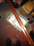
Bus bars finally arrived - these are solid copper bar and very meaty.

Can you tell this house is owned (oh ok then - RENTED) by an electronics/laser geek?
Next on the shopping list is a drill press and vice. There is NO way i am ruining these $75 bars! (yep $150 bux worth of copper there)
Can you tell this house is owned (oh ok then - RENTED
) by an electronics/laser geek?Next on the shopping list is a drill press and vice. There is NO way i am ruining these $75 bars! (yep $150 bux worth of copper there)
Attachments
Last edited:
- Joined
- Jan 13, 2010
- Messages
- 2,516
- Points
- 63
I like the random bits and bobs laying around on your floor 
vk2fro
0
- Joined
- Nov 30, 2009
- Messages
- 1,305
- Points
- 63
hehe I have since tidied up that area and pushed the big box-o-parts that is to be my cap bank against the wall out of the way. Those bus bars really hurt your shins if you run into them!
edit: Wooo just found a simplex 4040/vibratone 350 horn on ebay - finally I have the alarm that will sound before firing (aka geek group style). Needs 24AC, but a little stepdown transformer and a 200W inverter should do it.
edit: Wooo just found a simplex 4040/vibratone 350 horn on ebay - finally I have the alarm that will sound before firing (aka geek group style). Needs 24AC, but a little stepdown transformer and a 200W inverter should do it.
Last edited:
- Joined
- Sep 12, 2007
- Messages
- 9,399
- Points
- 113
Is there any reason why hammered copper pipe wouldn't work?