Welcome to Laser Pointer Forums - discuss green laser pointers, blue laser pointers, and all types of lasers

LPF Donation via Stripe | LPF Donation - Other Methods

Links below open in new window

ArcticMyst Security by Avery

B&W-tech Spectrometer & 473 module: Setup+Mods+Info

Joined
Jan 21, 2018
Messages
324
Points
43
Hi Chloderic,

No problem.
If you're wondering, I'm using a PIC24EP128GP202 for the MCU.
Considering the 8051 is 8 bits at 25 MIPS, and the PIC24 is 16 bits at 70 MIPS, there should be quite a noticeable difference in processing time, especially for short integration times.
There's plenty of ram for internal averaging and the data rate can be set above 115200 baud.
It may be a month or more before my next update as I'm quite busy with things of higher priority.

Hi Richard A, i am interested in this project, but i think i would not be able to solder smd .....


Joined
Mar 1, 2017
Messages
81
Points
8
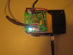
I finally received the PCBs and found some time to install a few components.
I'm happy the mounting holes line up perfectly.
Hopefully I'll have a working unit eventually.


View attachment 63018
Dear Richard,
I am sorry if i am that bad in electronics.
Do you mean that with this PCB you just need the optical banch and this green PCB to make the spectrometer work and work better?
can you, please, explane why you need this PCB board, is it just to make the spectrometer going fast?
does it improuve the data aquisition speed? what else are the benefits?
and where can we get this update?
Please, help :)
C
 
Last edited:
Joined
Jan 29, 2018
Messages
42
Points
8
Hi Richard A, i am interested in this project, but i think i would not be able to solder smd .....


Hi Chloderic,

Unfortunately, I had to mainly go with SMDs to keep the cost down.
Through-hole would require a larger PCB.
Also, some of the ICs are only available in surface mount packages, and the ones that are available in through-hole generally cost more.
 
Joined
Jan 29, 2018
Messages
42
Points
8
Dear Richard,
I am sorry if i am that bad in electronics.
Do you mean that with this PCB you just need the optical banch and this green PCB to make the spectrometer work and work better?
can you, please, explane why you need this PCB board, is it just to make the spectrometer going fast?
does it improuve the data aquisition speed? what else are the benefits?
and where can we get this update?
Please, help :)
C


Hi Civitus,

Yes, assuming one has cables, software, etc., all that would be required is this board attached to the bench.
I ruined the PCB on one of my spectrometers by using a 12 V adapter. Some of the damaged parts are user irreplaceable due to
read protection bits being set as uk-laser found out. I gave up trying to fix my board a while ago.
I figured if the CCD is still good, I should be able to test it with a MCU.
Initially, I made test setup using an old work project to confirm that the CCD did indeed still function.
After reading the CCD datasheet, I wrote some code, did a bit of soldering, and happily discovered that the CCD worked.
The CCD appears to be powered from a voltage regulator which is probably why it survived. The CPLD also clamped the voltage
down once it shorted.

Kecked suggested to share my design and make it open source.
I improved it since it wasn't much of a design to begin with.
My intent was to make low cost replacement PCB for units with irreparable boards.
The main benefits are faster acquisition times and data transfer rates.
ADC performance should be pretty close with the ADS8866.
There is also less risk of damaging the board since the main regulator (MIC5209-5.0YS) can tolerate 12 V.
My design will require 6 V minimum rather than 5 V fixed.


I now have two stuffed PCBs ready for programming.
This is a low priority project that I work on in my spare time so it might be a month before my next update.
I will provide links to the files once I get it mostly working.
 

pasajeros

New member
Joined
Feb 3, 2019
Messages
2
Points
3
Hi everyone, I am new to forums in general so please excuse me if I say or do anything wrong. So I bought one of the Pharmanex units about a year ago and now I'm ready to try and turn it into a complete RAMAN unit but I am going to take the spectrometer out and use an Ocean Optics spectrometer instead. The spectrometer already works great, it covers the wavelengths I need, it's plugs into a regular USB port, and I use Ocean Optics software that has a RAMAN featue in it. My question is, if I just substitute the Pharmanex spectrometer with my Ocean Optics one, will I have a complete RAMAN spectrometer? Is the probe already good enough to where I can start getting RAMAN spectrum from chemicals or minerals for example? If not, what would I have to buy or modify to get everything working as a complete turn-key RAMAN system? Thank you for everyone's help.
 
Joined
Jan 21, 2018
Messages
324
Points
43
Hi pasajeros, be welcome,

i have created a thread raman with the usage of components of this device here :


Maybe you could read this for additional infos ....

It would be fine to talk about raman here or there again .....

Greetings

Bernd
 
Joined
Jan 29, 2018
Messages
42
Points
8
Hi all,

Just a quick update to those who are interested.
I managed to find time to write some code (C and asm).
At the moment, everything appears to be working as expected, and there are no mods.
The spectrum readout looks good.
I did have swap the MCU with one that had a PWM on pin 26. Couldn't remap it.
Fortunately, I had a few laying around. Cost the same.
Should I continue posting updates to this thread or is it worth making a new one?

-Richard
 
Joined
Sep 20, 2013
Messages
17,414
Points
113
I can see no reason to stop posting this here. I'm sure there are some who have lost one of these spectrometers to using a +12 volt supply, so any information on how to proceed after that is good information.
 
Joined
Jan 29, 2018
Messages
42
Points
8
I can see no reason to stop posting this here. I'm sure there are some who have lost one of these spectrometers to using a +12 volt supply, so any information on how to proceed after that is good information.

Hi Paul,

Well, I suppose I'll leave it where it is then.
I'm kind of glad I started this project because one of my once good
B&W spectrometers is now having intermittent issues; sometimes it locks up when powering on.
 
Joined
Jan 21, 2018
Messages
324
Points
43
Hi Paul,

Well, I suppose I'll leave it where it is then.
I'm kind of glad I started this project because one of my once good
B&W spectrometers is now having intermittent issues; sometimes it locks up when powering on.
I also ask you to go on posting here, thanks for the information ....
For your actual problems with this device ...i would try an other usb to ser stick , it sounds like timing-problems i had also.
Greetings
Bernd
 
Joined
Sep 20, 2013
Messages
17,414
Points
113
Hi Paul,

Well, I suppose I'll leave it where it is then.
I'm kind of glad I started this project because one of my once good
B&W spectrometers is now having intermittent issues; sometimes it locks up when powering on.
You can see that we are now posting into the 800s on these units, so this is becoming quite comprehensive on these spectrometers. You can likely find the answers to many questions about these spectrometers by just reading all of the posts. I have not personally done anything with mine in awhile now. But, I am still interested in getting as much information as possible in this thread. Thanks.
 
Joined
Jan 29, 2018
Messages
42
Points
8
I also ask you to go on posting here, thanks for the information ....
For your actual problems with this device ...i would try an other usb to ser stick , it sounds like timing-problems i had also.
Greetings
Bernd

I'm actually using a PCI serial port card, and the spec locks up with no serial cable connected.
I've never had any of the other good spectrometers do this.
They usually spit out a bit of data on power up with the led momentarily going green.
 
Joined
Jan 21, 2018
Messages
324
Points
43
I'm actually using a PCI serial port card, and the spec locks up with no serial cable connected.
I've never had any of the other good spectrometers do this.
They usually spit out a bit of data on power up with the led momentarily going green.
Please connect the spec with the ser cable to the ser card of your PC without powering the spec, than start a terminal program, than power the spectrometer and post here the end of the pre-message you see in the terminal window.
 
Joined
Jan 29, 2018
Messages
42
Points
8
Please connect the spec with the ser cable to the ser card of your PC without powering the spec, than start a terminal program, than power the spectrometer and post here the end of the pre-message you see in the terminal window.

When working, everything appears normal and it scans fine.
It does not lock up often. When it does lock up, no data ever comes out, and the LED always remains red.

This is the output from CuteCom on Debian:

Code:
*************************************
***        B&W TEK, INC.          ***
***  Your Solution Provider       ***
***  WWW.BWTEK.COM                ***
***  TEL:302-368-7824             ***
***  Fax:302-368-7830             ***
*************************************

********************************************
**  Model:BTC110-S    For Nuskin          **
**  Version:#6488                         **
**  Release date:  Apr 18,2003            **
**  e-mail: support@bwtek.com             **
********************************************
**  Error codes=0                         **
**  Functional test: Passed!              **

One thing I noticed on this spectrometer is that the screws are a bit rusty.
The other spectrometers are clean. The PCB doesn't look bad but there could be an intermittent via.
 
Joined
Jan 21, 2018
Messages
324
Points
43
Hi Richard A,

as you see there was no error while booting in this case.
As you know, such errors (which are not always seen) are not easy to be defined.
Maybe you should repeat multiple boots of the device in the hope to see an error-code .
You can see such a typical error here in the post #491 .

** Error codes=8101 **
** Functional test: Failed **

This was a timingproblem with the serial port.

Greetings

Bernd
 
Joined
Jan 29, 2018
Messages
42
Points
8
Hi Richard A,

as you see there was no error while booting in this case.
As you know, such errors (which are not always seen) are not easy to be defined.
Maybe you should repeat multiple boots of the device in the hope to see an error-code .
You can see such a typical error here in the post #491 .

** Error codes=8101 **
** Functional test: Failed **

This was a timingproblem with the serial port.

Greetings

Bernd


Hi Chloderic,


I did get the spectrometer to fail again. I gave it a few taps and it started working with no error codes.
There must be a bad connection somewhere.

I found some time to write more code and to some testing.
Hopefully, I'll be able to release the project this month.
The alignment on both spectrometers is poor, especially the one that has my replacement PCB installed.
They both need to be realigned.
Looks like my sampling is off 1 pixel. Need to fix that.
On the stock PCB, the -3 dB cutoff of the opamp is set between 8 kHz and 10 kHz.
Feedback resistor is 335 kΩ with a 56 pF (it might be 47) cap. 1/(2πrc).
I tested mine at two different bandwidths. If someone were to install a smaller slit they may want to increase the bandwidth.
Flash routines need to be written so that settings and calibration coefficients can be stored to the dsPIC's flash.
Code for the processor's internal 12-bit ADC also needs to be written.
I'm not positive how the temperature is being read as I don't see a temperature sensor anywhere.
Perhaps they're using the offset voltage of the CCD. It does vary with temperature.


New features:

The baud rate can be set to 921600.
I was only able to test it to 576000 do to computer hardware issues.
Very fast with compression mode on.
Offset can be tweaked as well as auto leveled.

63899

63900

63901

6390263903


Top