Dear Richard,
I am sorry if i am that bad in electronics.
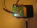
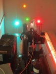
Do you mean that with this PCB you just need the optical banch and this green PCB to make the spectrometer work and work better?
can you, please, explane why you need this PCB board, is it just to make the spectrometer going fast?
does it improuve the data aquisition speed? what else are the benefits?
and where can we get this update?
Please, help

C
Hi Civitus,
Yes, assuming one has cables, software, etc., all that would be required is this board attached to the bench.
I ruined the PCB on one of my spectrometers by using a 12 V adapter. Some of the damaged parts are user irreplaceable due to
read protection bits being set as uk-laser found out. I gave up trying to fix my board a while ago.
I figured if the CCD is still good, I should be able to test it with a MCU.
Initially, I made test setup using an old work project to confirm that the CCD did indeed still function.
After reading the CCD datasheet, I wrote some code, did a bit of soldering, and happily discovered that the CCD worked.
The CCD appears to be powered from a voltage regulator which is probably why it survived. The CPLD also clamped the voltage
down once it shorted.
Kecked suggested to share my design and make it open source.
I improved it since it wasn't much of a design to begin with.
My intent was to make low cost replacement PCB for units with irreparable boards.
The main benefits are faster acquisition times and data transfer rates.
ADC performance should be pretty close with the ADS8866.
There is also less risk of damaging the board since the main regulator (MIC5209-5.0YS) can tolerate 12 V.
My design will require 6 V minimum rather than 5 V fixed.
I now have two stuffed PCBs ready for programming.
This is a low priority project that I work on in my spare time so it might be a month before my next update.
I will provide links to the files once I get it mostly working.


