Welcome to Laser Pointer Forums - discuss green laser pointers, blue laser pointers, and all types of lasers

LPF Donation via Stripe | LPF Donation - Other Methods

Links below open in new window

ArcticMyst Security by Avery

ARDUINO & DAC for XY projector

camvo

0
Joined
Sep 25, 2011
Messages
102
Points
0
Hi all!

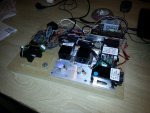
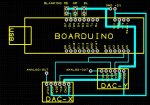
I have made an Arduino (Boarduino) based DAC for a laser scanner.

I have put the basic setup in the attached images with some results.

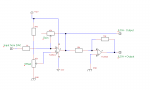
Basically you connect the output from the DAC-s, after processing to a -5V/+5V signal, directly to the scanner's ampliefier boards.

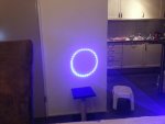
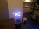
Some fancy (or not) programming of the Arduino and the scanners draw lines or dots on the wall.

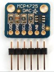
I used 2 pieces MCP4725 DAC-s from sparkfun. You can use 2 DAC-s on the I2C of the Arduino because you can give the DAC-s separate addresses by putting the ADDR (address) pin to 5V or not.

The lasers are a 1W RGB set, the scanner is 20kpps.

I need to figure out how to make the circle more smoother.
Now it is a stepped circle which kind of gives a nice effect but it is not what I want.
This is because the micro processor can only do one thing at a time.
The out put of the DAC-s now is straight and one to one so the projector can not draw diagonal lines. (Not yet...)

I need the help of electronics professionals because I am obviously not!! :p
Any ideas are welcome.....
 

Attachments

  • circle.jpg
    circle.jpg
    307.4 KB · Views: 9,597
  • dancing waves.jpg
    dancing waves.jpg
    308.5 KB · Views: 2,509
  • projector setup.jpg
    projector setup.jpg
    409.3 KB · Views: 3,623
  • PRINCIPLE XY projector.JPG
    PRINCIPLE XY projector.JPG
    482.1 KB · Views: 4,501
Last edited:


Joined
Apr 2, 2009
Messages
10,662
Points
113
Great thread--+3 to your rep from me.
A few times in the past I have seen threads offering items like yours- instead of asking for payment some will just ask for a 'donation' to help cover some of thier expenses. Some may send nothing, some may send the amount you wanted , while others. may even send you more.. very few members here will take advantage of you.


Almost every member has interest in laser harps-- there are many posts and threads here and at the lasershow forums.. the riches we get from this forum is not always in the form of money.
Hard to put a price on friendship. Favors done come back two-fold,
V/R--- len

BTW just did a search for 'laser harp' and got three pages of posts.
two notable are from/about members 'Things' and 'csshih'..
 
Last edited:
Joined
Feb 10, 2012
Messages
330
Points
0
+1 Camvo, REP to you.

You might be liminted by the bandwidth of the I2C bus.
You need to calculate the number of co-orddinates you can transfer to the D to As... or the tome delay between sending the X and then y co=ordinate - these should be output symiltaniously or you will get a stair case effect ;-)

You might need to use a parallel data bus D to A converter.
Alternatively, is it possible to increase the number of co-ordinates?
Are these calculated on the fly or being retreived from a data table.

years ago i made a galvo driver using a 1Mhz 6502 processor which produced smooth circles/ shapes / logos, but i was using parallel D to A chips.

ATB
MM

Edit, just scanned the data sheet - the D to A can run in 100khz, 400khs or 3.4mbps mode, so the chip should be fast enough.
Prob is likely to be the Arduino I2C libriary is bit banged and not using the I2c hardware on the processor chip which is causing the delay between the X and Y co-ords being sent out.
 
Last edited:

camvo

0
Joined
Sep 25, 2011
Messages
102
Points
0
THX hakzaw1


I used this MCP4725 DAC. It is very easy to program.

After the DAC, I used the correction amp circuit of Benm which I found on LPF to convert the 0/+5V signal from the DAC to a -5V/+5V for the Galvo amplifierboard.
Since there are 2 DAC-s, Benm's circuit is used 2 times, one for each DAC.

Only thing to solve is how to smooth out the steps.
 

Attachments

  • DAC MCP4725.JPG
    DAC MCP4725.JPG
    215.2 KB · Views: 1,454
  • correction-amp.png
    correction-amp.png
    5.4 KB · Views: 3,260

camvo

0
Joined
Sep 25, 2011
Messages
102
Points
0
@ Multimode

The DAC is 12bit so you have a 4096x4096 grid to draw figures on it.
The code calculates the X and Y coordinates and then these are set first by DAC-X and then DAC-Y.

red(); // turns on the red laser
for (times = 0; times < 15; times++)
{
for (int grad = 0; grad < 360; grad=grad+10)
{
float rad = 2*pi * (grad/360.0);
valx = cos(rad)*2000 + midx;
valy = sin(rad)*2000 + midy;
setx();
sety();
}
}

The staircase is also caused because I use a 10 degree step for the next point in the circle. By increasing the resolution of the circle it will probably get smoother but the image starts to show an annoying flickering.

I have no idea how to use a parallel data bus D to A converter.
Sounds very complicated to me!
 
Last edited:

Things

0
Joined
May 1, 2007
Messages
7,517
Points
0
Are you using any pre-existing libraries for the DAC? A fair bit of Arduino code I've seen (and some I've written myself, I'll admit) is far from optimized for speed. A serial DAC is more than fast enough, it's just the code you need to optimize.

I think some math in your code is wrong however, as those dots are more in a staircase rather than a circle, which is why increasing the resolution would cause flicker.
 
Joined
Oct 26, 2007
Messages
5,438
Points
83
Very nice work! Programmatic patterns are always cool. You can also use a buffer to store pre-computed points. However, you're going to be severely limited by RAM on a plain Arduino. You might want to look into an Arduino Due, or something else that has more RAM/capabilities. It'll also operate faster so you can pump out more points to smooth out things.

Look into performing direct port manipulation to speed up things. Also avoid per-point calculations, especially those that involve floating point numbers -- at least on slower processors like the ATmegas.

Here's some example code demonstrating a point buffer (I call it a canvas). I can't guarantee it's fully working, so you'll have to fill in the blanks:

Code:
#include <stdio.h>
// Other includes

// Number of points will be limited by the RAM in the microcontroller
#define NUM_POINTS      100

        // Adjust as needed with respect to the number of points
#define DELAY_FACTOR    50

// 5-pointed star:
#define STAR_SCALE      5

// Defined clockwise from top point:
#define STAR_0_X        0
#define STAR_0_Y        (60 << STAR_SCALE)
#define STAR_1_X        (60 << STAR_SCALE)
#define STAR_1_Y        (21 << STAR_SCALE)
#define STAR_2_X        (40 << STAR_SCALE)
#define STAR_2_Y        ((int)(-50) << STAR_SCALE)
#define STAR_3_X        (-STAR_2_X)
#define STAR_3_Y        STAR_2_Y
#define STAR_4_X        (-STAR_1_X)
#define STAR_4_Y        STAR_1_Y


// Bit-packed coordinate and colors into 32-bits:

struct Coordinate
{
    unsigned int        x       : 12;
    unsigned int        y       : 12;
    unsigned char       color   : 8;
};

Coordinate canvas[NUM_POINTS];


void setup()
{
    // Initialization stuff here

    // Zero canvas:
    memset(canvas, 0, NUM_POINTS);

    // Draw something:
    Coordinate * coord = &canvas[0];

    // 5-point star

    for(int n = 0; n < 5; ++n)
    {
        int x0, y0, x1, y1;
        switch(n)
        {
        default:
        case 0: // 0 -> 2
            x0 = STAR_0_X;
            y0 = STAR_0_Y;
            x1 = STAR_2_X;
            y1 = STAR_2_Y;
            break;
        case 1: // 2 -> 4
            x0 = STAR_2_X;
            y0 = STAR_2_Y;
            x1 = STAR_4_X;
            y1 = STAR_4_Y;
            break;
        case 2: // 4 -> 1
            x0 = STAR_4_X;
            y0 = STAR_4_Y;
            x1 = STAR_1_X;
            y1 = STAR_1_Y;
            break;
        case 3: // 1 -> 3
            x0 = STAR_1_X;
            y0 = STAR_1_Y;
            x1 = STAR_3_X;
            y1 = STAR_3_Y;
            break;
        case 4: // 3 -> 0
            x0 = STAR_3_X;
            y0 = STAR_3_Y;
            x1 = STAR_0_X;
            y1 = STAR_0_Y;
            break;
        }

        // Linear interpolation:
        int dx = (x1 - x0) / (NUM_POINTS / 5);
        int dy = dx * (y1 - y0) / (x1 - x0);

        // We recycle x0, y0 as our working coordinates.   Center the
        // coordinates at the center of the screen:
        x0 += 2048;
        y0 += 2048;
        char c = 1; // Variable to determine whether the color is on or off.

        for(int i = 0; i < (NUM_POINTS / 5); ++i, ++coord)
        {
            coord->x = x0;
            coord->y = y0;
            coord->c = c;
            c = !c; // make the lines dashed
            x0 += dx;
            y0 += dy;
        }
    }
}


void loop ()
{
    Coordinate * coord = &canvas[0];

    for(int i = 0; i < NUM_POINTS; ++i, ++coord)
    {
        // Whatever code for sending the bytes
        Wire.beginTransmission(X_ADDR);
        Wire.send(0xFF & coord->x); //  LSB
        Wire.send(0xFF & (coord->x >> 8)); // MSB
        Wire.endTransmission();
        // Whatever code for sending the bytes
        Wire.beginTransmission(Y_ADDR);
        Wire.send(0xFF & coord->y); //  LSB
        Wire.send(0xFF & (coord->y >> 8)); // MSB
        Wire.endTransmission();
        if (coord->c)
        {
            bitSet(PORTD, 4); // Or wherever it's set
        } else {
            bitClear(PORTD, 4);
        }

        delayMicroseconds(DELAY_FACTOR);
    }
}
 
Joined
Oct 26, 2007
Messages
5,438
Points
83
You can use that "c" to look up colors from a table, or just switch channels on or off, e.g.

Code:
#define SET_R(C)    (C |= (1 << 0))
#define SET_G(C)    (C |= (1 << 1))
#define SET_B(C)    (C |= (1 << 2))
#define CLEAR_R(C)  (C &= ~(1 << 0))
#define CLEAR_G(C)  (C &= ~(1 << 1))
#define CLEAR_B(C)  (C &= ~(1 << 2))

...

char color = 0;
SET_R(c);
CLEAR_B(c);
SET_B(c);
coord->c = c;

...

// Red
if (coord->c & 1)
{
    bitSet(PORTD, 4); // Or wherever it's set
} else {
    bitClear(PORTD, 4);
}

// Green
if (coord->c & (1 << 1))
{
    bitSet(PORTD, 5); // Or wherever it's set
} else {
    bitClear(PORTD, 5);
}

// Blue
if (coord->c & (1 << 2))
{
    bitSet(PORTD, 6); // Or wherever it's set
} else {
    bitClear(PORTD, 6);
}
 

camvo

0
Joined
Sep 25, 2011
Messages
102
Points
0
@ Things

I use the standard included wire library.

And I admit....I am a bit rusty on the math. Give me a break. That was 20 years ago!
 

camvo

0
Joined
Sep 25, 2011
Messages
102
Points
0
@ Bionic-Badger

Thanks for the tips. I will give it a go tonight.

If I can get it to work, it might be useful for the laser harp as well and improve the visibility of the beams!!!
 
Joined
Feb 10, 2012
Messages
330
Points
0
@ Multimode

The DAC is 12bit so you have a 4096x4096 grid to draw figures on it.
The code calculates the X and Y coordinates and then these are set first by DAC-X and then DAC-Y.

The staircase is also caused because I use a 10 degree step for the next point in the circle. By increasing the resolution of the circle it will probably get smoother but the image starts to show an annoying flickering.

I have no idea how to use a parallel data bus D to A converter.
Sounds very complicated to me!

Hi Camvo,

As you are calculating the x and y co-ords first , then sending the data to the DtoA together, (which is good) the delay must be due to the slow Wire lib.
Even with a small number of co-ords you still should get a direct line between your programmed points.
As the galvos have a 1 or 2ms response (ish), you need to make sure that the x and y co-ord pair are output by the D-to As simultaneously.

As Bionic Badger has suggested, you might need to junk the wire lib and control the port from your own code to get the response you're looking for.

As a simple experiment, you could just output 2 co-ordinates to form a diagonal line. You should get a line between the two co-ords, if there is a square corner, then you need to focus on getting delay between sending X and Y pairs to a minimum.

Great Job you're doing there and look forward to seeing the project progress:beer:
Seeing this make me want to get a pair of Galvos too :)

ATB
MM
 

camvo

0
Joined
Sep 25, 2011
Messages
102
Points
0
@ Bionic-Badger

I could not make much of the code because I could not realy understand what is going on.

Additionally the compiler was complaining about:

'struct Coordinate' has no member named 'c'


This was my original code:

Code:
#include <Wire.h>
#define DACX 0x63 
#define DACY 0x62 

// pin definitions

int lred   = 6;  // blanking pin red 
int lgreen = 5;  // blanking pin green 
int lblue  = 3;  // blanking pin blue

// variables 

int pause = 50;         // mirror pause
int times = 0;
int grad = 0;
float rad = 0;
float pi = 3.14;

int midx       = 2040;      // master center for x
int midy       = 2040;      // master center for y
int valx * * * = 2040; * * *// set the x-coordinate to center
int valy * * * = 2040; * * *// set the x-coordinate to center

void setup()
{
  Wire.begin();
  Serial.begin(9600);
  pinMode(lred,   OUTPUT);
  pinMode(lgreen, OUTPUT);
  pinMode(lblue,  OUTPUT);

  digitalWrite(lred,  LOW);
  digitalWrite(lgreen, LOW);
  digitalWrite(lblue, LOW);
  
  black(); // lasers off

} // end void setup

void loop()
{
  green();
  for (times = 0; times < 15; times++)
  {
  for (int grad = 0; grad < 360; grad=grad+10)
  {
   float rad = 2*pi * (grad/360.0);
   valx = cos(rad)*2000 + midx;    
   valy = sin(rad)*2000 + midy;
   setx();
   sety();
  }
  }
  
 } // end loop

//***************************************
//              functions 
//***************************************


void setx()
{
 Wire.beginTransmission(DACX);  
 Wire.send(64);                // cmd to update the DAC  
 Wire.send(valx >> 4);         // the 8 most significant bits...
 Wire.send((valx & 15) << 4);  // the 4 least significant bits...
 Wire.endTransmission();
}
 
void sety()
{
 Wire.beginTransmission(DACY);  
 Wire.send(64);                // cmd to update the DAC  
 Wire.send(valy >> 4);         // the 8 most significant bits...
 Wire.send((valy & 15) << 4);  // the 4 least significant bits...
 Wire.endTransmission();
}

void black()
{
 digitalWrite(lred,   LOW);
 digitalWrite(lgreen, LOW);
 digitalWrite(lblue,  LOW);  
}

void green()
{
 digitalWrite(lred,   HIGH);
 digitalWrite(lgreen, HIGH);
 digitalWrite(lblue,  HIGH);
}
 
Last edited:

camvo

0
Joined
Sep 25, 2011
Messages
102
Points
0
But changed it to this:

Code:
#include <Wire.h>
#include <stdio.h>
#define DACX 0x63 
#define DACY 0x62 

// pin definitions

int lred   = 6;  // blanking pin red 
int lgreen = 5;  // blanking pin green 
int lblue  = 3;  // blanking pin blue

// variables 

int pause = 50;         // mirror pause
int times = 0;
int grad = 0;
float rad = 0;
float pi = 3.14;

int midx       = 2040;      // master center for x
int midy       = 2040;      // master center for y
int valx       = 2040;      // set the x-coordinate to center
int valy       = 2040;      // set the x-coordinate to center

void setup()
{
  Wire.begin();
  Serial.begin(9600);
  pinMode(lred,   OUTPUT);
  pinMode(lgreen, OUTPUT);
  pinMode(lblue,  OUTPUT);

  digitalWrite(lred,  LOW);
  digitalWrite(lgreen, LOW);
  digitalWrite(lblue, LOW);
  
  black(); // lasers off

} // end void setup

void loop()
{
  green();
  for (times = 0; times < 15; times++)
  {
  for (int grad = 0; grad < 360; grad=grad+10)
  {
   float rad = 2*pi * (grad/360.0);
   valx = cos(rad)*300 + midx;    
   valy = sin(rad)*300 + midy;
   setx();
 //  sety();
  }
  }
  
 } // end loop

//***************************************
//              functions 
//***************************************


void setx()
{
// hier het origineel
 Wire.beginTransmission(DACX);
 Wire.send(0xFF & (valx >> 8)); // MSB Wire.send(valx >> 4);          // the 8 most significant bits...
 Wire.send(0xFF & valx);        // LSB  Wire.send((valx & 15) << 4);  // the 4 least significant bits...
 Wire.endTransmission();
 // Whatever code for sending the bytes
 Wire.beginTransmission(DACY);
 Wire.send(0xFF & (valy >> 8)); // MSB  Wire.send(valy >> 4);         // the 8 most significant bits...
 Wire.send(0xFF & valy);        // LSB  Wire.send((valy & 15) << 4);  // the 4 least significant bits...
 Wire.endTransmission();

}

void black()
{
 digitalWrite(lred,   LOW);
 digitalWrite(lgreen, LOW);
 digitalWrite(lblue,  LOW);  
}

void green()
{
 digitalWrite(lred,   LOW);
 digitalWrite(lgreen, HIGH);
 digitalWrite(lblue,  LOW);
}
 

camvo

0
Joined
Sep 25, 2011
Messages
102
Points
0
I changed 2 things:

The order of the sending the bytes.
I hate to be a smart axx but I think you should send the MSB first and then the LSB.

Wire.beginTransmission(X_ADDR);
Wire.send(0xFF & coord->x); // LSB
Wire.send(0xFF & (coord->x >> 8)); // MSB
Wire.endTransmission

This gave me only a horizontal line and a vertical line

changed to:

Wire.beginTransmission(DACX);
Wire.send(0xFF & (valx >> 8)); // MSB
Wire.send(0xFF & valx); // LSB
Wire.endTransmission();


Additionally I changed the scale.

valx = cos(rad)*2000 + midx;
valy = sin(rad)*2000 + midy;

changed to:

valx = cos(rad)*300 + midx;
valy = sin(rad)*300 + midy;

That gave a much better result.
By multiplying the coordinates with 2000:
Yeah, of course the circle gets course.

I need to find a faster way to update the xy position almost synchronized.

Can that be done with direct port manipulation?
Because I think, as multimode said, I need a faster way than the "wire.send" command.
 

Attachments

  • green circle 300.jpg
    green circle 300.jpg
    322.9 KB · Views: 1,564
Last edited:

camvo

0
Joined
Sep 25, 2011
Messages
102
Points
0
and the dancing worms.

Naturally, also staircased.
 

Attachments

  • worms.wmv
    1.9 MB · Views: 283
Last edited:


Top