They probably are better, but we don't know what size, focal length we need, and where to get one with the AR coating.
Hopefully someone figures it out soon
I just wish we could find out the EXACT specs or maker of the 445nm laser diodes and get their Parallel and perp far field patterns & other data. I'm sure they were made especially for Casio. If we just knew.
Well...yes...we are at the early stages of the 445LD understanding....optically electrically and thermally. To extend our knowledge of these amazing coherent light engines...many, many trials and experiments will and should unfold. We will go down many " Dead Ends "...no doubt !! Perhaps Cylinderical Lenses are the best optical solution. Unlike Anamorphic Prisms...there are a vast array of lens geometries to choose from...not a quick or simple project !!! WAY outta my league !!!
Dr. Lava sez that these 1W 445nm diodes are more optically challenging than the 445LD's used in the Kvant Projectors and that is why for projector application he will be using Cylinderical Lenses to tame this beam.
But for pointer application...perhaps the use of Anamorphic Prisms will be sufficient....if the transmission loss can be reduced ?? You could also take the position that the Larry DFW 445 lens could be considered adquate for a pointer application...with NO optical loss to deal with !! ?? Engineering is always a matter of compromises and this LD surly presents a fair amount of technical challenges. Thanx for your comments !!! CDBEAM
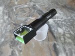
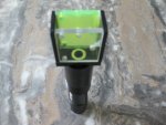
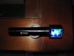
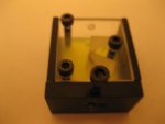
Pictures below are the latest upgrade of my anamorphic prism holder attached to the Jayrob 532 DIY. The clamping assembly is now reinforced with sides and a back plate. This plate is bored out to accept the focus ring of the Larry DFW 445 lens unit. Top and bottom of the focus ring bore is drilled and threaded to utilize two 6-32 set screws. These screws then secure the unit to the focus ring in a very solid fashion. This is ONE way to do it. I am sure there are many ways.
I have also located a set of anamorphic prisms made from BK7 glass and coated for 445nm. According to the manufacture…the transmission loss is predicted to be < 10%. We will see what can be achieved!!! In my opinion…10% T-loss at 1 mrad is very acceptable!! Thanx….CDBEAM
That is looking like a sweet little build. Very professional look to it for a hobby build. How do you focus it? Do you focus it first then attach the prism box?
Nice looking build. Mine looks almost identical except without the prisms. It's also set to the same current and has about the same output. Good luck in getting better optics to reduce the transmission loss.
Thanx for the comments !! Think about this...What we do now...as far as experimentation MAY be VERY usefull when GREEN Direct injection diodes are introduced...likely in the not too distant future....!!!!
Morgan...I focus to infinity first...then secure the ASA
X101...Optics are ordered...prisms are slightly smaller than the current set !!! I cannot see the need to employ Cylindrical Lenses in a pointer application....Overkill !!!
Two things I would like....a more massive copper heatsink....about twice as big as this build and a much tighter fit between the LarryDFW lens threads and the AxisZ 12 x 30 module !!! Why is the fit as sloppy as it is ??? IS there another press fit module with a tighter fit ???? ( MMM ??...no off-topic comments please)...Thanx...CDBEAM
My background is in semiconductor manufacturing so I am familiar with thin film coatings first hand but not real familiar with optics. What material are they using for an AR coating on the prisms. I used to manage a small MEMS lab for a highly rated engineering college and have done some thin film coating on prisms for one of the physics professors who was doing research on Plasmons. Now I wish I still had access to my old sputtering system. If anyone is familiar with the material used for the film and even a rough idea of the thickness I would appreciate the info.
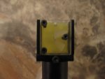
To secure the lens unit to the AixiZ module...I drilled a 7/64 bore about 1/16" from the edge of the AixiZ case ( Short section where the diode is pressed into ). This hole is then tapped with a 6-32 NC tap. A 6-32 set screw is then used to engage the threads of the lens unit. This method really makes the lens unit steady. I would add two notes: Only apply enouge torque to snug up the lens to the holder and do NOT drill the hole TOO close to the edge...or you will not be able to completely screw on the focus ring !!
This is ONE way to do it....so then...you focus and tighten the set screw...and the lens unit will stay put and have no movement that I can see....mmm..."set it and forget it" !!!
Maybe that is just the tollerance available for the module/lens units ??? Using teflon tape works....but seems a bit absurd !! I do not understand the loose fit ??????
I suppose if you wanted to get real AR about this....you could drill and tap three (3) holes at 120 degree to each other...and use three (3) set screws to apply equal pressure in three spots on the lens OD ???...well...I am AR....but not THAT bad !! I am still waiting on more prism sets to continue the Anamorphic experiments....and I have no idea what the coating is....just that it is there !!! CDBEAM
Larry: I have two sets of prisms shipping from different sources at PL. I am confident that the losses can be reduced to 3~5 %....but what of the fast axis divergence. Currently I can get down to about 1.5 mrad on the fast axis. This still projects a rectangle geometry of 25mm x 6mm at 45'. Perhaps I do not have the prisms at the best position. I am experimenting with this. There seems to be little information on what is the best position for the prisms...and what info is out there is somewhat different from source to source. Perhaps the optimal position must be determined by manufacture....and this is why there are many different solutions offered ??????
As to the issue of a loose fit between module and lens...DOC at PL noted that the Focus Ring aperature could be opened up to 9.5mm bore...then the Focus ring acts as a slip nut...and once focus to infinity is acheived...the nut can be tightened up against the lip of the AixiZ module. This is fine...if you do not want to adjust the focus...and with this diode...anything other than to infinity I think is useless. Thanx for your interest...Later...CDBEAM
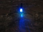
Kinda like the Thomas Edison method....Trial and error !!!.. Well the trial and error continues. Although I have now been able to reduce the fast axis mrad to about 1.3 ....this still generates a rectangle ( 7/8" x 1/4" ) and not a square at around 45 feet.....the bottom line is...what does the user want, how large will the optics add-on be and what is the hobbyist willing to pay for ????
Is the beam shape to 7/8" x 1/4" at 45 feet acceptable ??? Will different prism sets from different manufactures deliver improved beam geometry ??? Will cylindrical lenses offer the ultimate toward delivering a square beam pattern ???
Two cylindrical lenses are required to beam shape an eliptical LD output....such an arrangment is larger than a small prism set....so this is not good !! Well... the search for the perfect optics goes on....Later...CDBEAM
As soon as I get my AixiZ modules, I'm bringing my 445nm laser over to a friend who's an optic expert. I'll report back here what he suggests to correct for the fast axis.


")