Welcome to Laser Pointer Forums - discuss green laser pointers, blue laser pointers, and all types of lasers

Buy Site Supporter Role (remove some ads) | LPF Donations

Links below open in new window

FrozenGate by Avery

40mW Sanyo 635nm LDs on Ebay

Bleh, this diode is starting to become a pain in the ass. I don't want to go through the trouble of getting a green module, I'd rather use a boost.

Why do you think this will not work though?

MFO the problem here is that the ehgemus host with a direct press head cannot be isolated from the case. Whichever driver you end up using in this host it will have to be set up case positive which will mean the positive of the battery will flow through the host directly into the diode so you will need to regulate the current from the isolated negative side. The flexdrive regulates via the positive side and would be bypassed altogether in this host with this diode.

There are a few drivers and that you can buy that regulate via the negative. I have a 14650 host. The Aixiz is one but was a little long to fit in my ehgemus module but an 18650 host should have a slightly bigger driver pocket. I ended up using this odicforce driver. Variable Current Step-up (Boost) 405nm Laser Driver Board - Detailed item view - OdicForce Lasers Online Shop

I had to cut the driver down a little but I got it to fit. The lines where where I cut the board.

p1015609.jpg


Here is mine.:D

p1015623.jpg
 
Last edited:


Bleh, this diode is starting to become a pain in the ass. I don't want to go through the trouble of getting a green module, I'd rather use a boost.

Why do you think this will not work though?


I bet there are a few people on the board who would love to buy it off you.
 
Forgive the noob question, but why can't you put a linear regulator on the negative side?
 
Last edited:
like an IR pump, when you look at the bottom you see the case pin which is the anode
for this diode. The next pin counterclockwise is the cathode. The other pin opposite
the cathode is sensor feedback/unused.
 
Last edited:
like an IR pump, when you look at the bottom you see the case pin which is the anode
for this diode. The next pin counterclockwise is the cathode. The other pin opposite
the cathode is sensor feedback/unused.

So, if I'm going case positive then the only pin I really need to solder to the driver is pin # 3, correct?

ucsPB.png
 
yeah careful how the numbered pins are in the schematic "top view", means your
looking into the diodes window, the pins are on the backside, so don't get 1 and 3 mixed up.
 
  • Like
Reactions: mfo
2pcs constant current laser diode driver 80-500mA w/TTL, AixiZ

So basically, pin 1 goes to the LD- side, and I can solder pin 3 to the LD+ side of the driver, correct? Or should I just solder pin 1 to the board and call it a day?

Thanks so much for your help guys. Had it not been for you guys, I'd have killed this diode 9 times over lol

Have you gotten those drivers to work before? I had 4 of them and ended up throwing them away after just trying to get past the damn TTL in a handheld.

EDIT: I had a different driver model but it also had TTL
 
Last edited:
2pcs constant current laser diode driver 80-500mA w/TTL, AixiZ

So basically, pin 1 goes to the LD- side, and I can solder pin 3 to the LD+ side of the driver, correct? Or should I just solder pin 1 to the board and call it a day?

Thanks so much for your help guys. Had it not been for you guys, I'd have killed this diode 9 times over lol


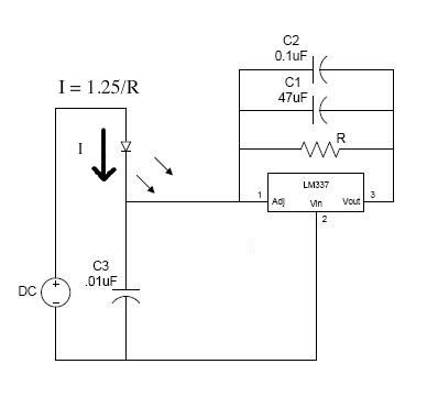
Looking at the driver it is LM358 (opamp based) so it should work. But without knowing the circuit I cannot tell you. Personally I would get a green laser driver or a LM337 driver. I have used both and they both work great.
 
Ok I just finished my micro lm317 driver for ~ 100ma really about 96 but it will fit in a pen and that is what I care about.

40mW 635nm should be as bright or brighter than 200mW 660nm right? Also, are these single mode?


Back
Top