Welcome to Laser Pointer Forums - discuss green laser pointers, blue laser pointers, and all types of lasers

Buy Site Supporter Role (remove some ads) | LPF Donations

Links below open in new window

FrozenGate by Avery

200mW of green for $125 shipped!!!!!!!!!!!!!

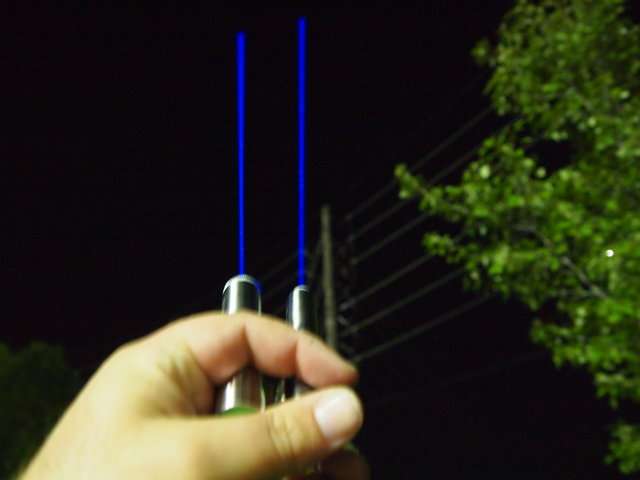
Nice pics. Are these extended exposures? That laser looks like at least 400mw.

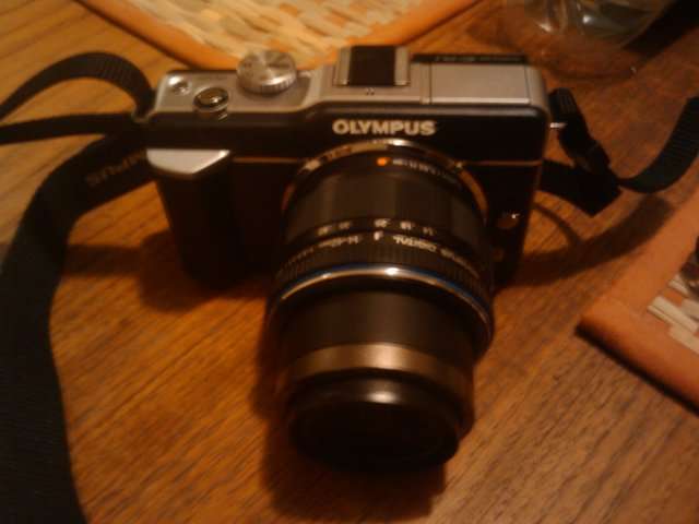
I just got this camera and have no idea what any of the setting are yet. Never been into photography but really wanted something nice. At the moment I am using just the auto setting and point and click. It is an Olympus E-PL1. The biggest thing I hope it can do is let me change the color somehow because my 405 is showing up like 445.

405 on the left 445 on the right
p1010394y.jpg

20100917221006.jpg


Hey, nice coffee table.

Thanks. It doubles as my workbench.:D
 
Last edited:


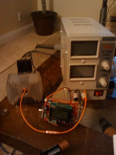
I ordered my +150mW DPSS analog on Sunday 9/19/2010 and today (1 day later) it was shipped! I don't think there are any delys with shipping because of the chinese holiday. By the way, I noticed a big silver "PC power supply" on your coffee table. What exactly is that?

I have heard of people making regulated power supplies from computer parts that have potentiometers to adjust the current and/or voltage. Does anyone know of good tutorial on how to do that?
 

Attachments

  • ss.gif
    ss.gif
    8.1 KB · Views: 87
paul, you ordered yours the day before me and I was told I'd have to wait for mine to be shipped! I hope they aren't telling me porky pies... I hate being lied to. Still, give them the benefit of the doubt, can't do much else can I!?

EDIT: Just received an email, talk about timing. My laser has been dispatched. Now we wait...
 
Last edited:
By the way, I noticed a big silver "PC power supply" on your coffee table. What exactly is that?


It is my bench power supply. It has adjustable voltage and current. Runs of the wall outlet. You can check my sig for bench tests.
20100903220712.jpg


Here is a test trying to kill an A140 diode.


Well this is frustrating. I just hooked my analog one up to a 5V power supply and the laser won't turn on. Unless the delay is super long (> 1minute) or I'm doing something completely wrong, I think mine is broken.

Edit, never mind I got it working. It turns out the modulation wires coming out of the driver were mixed up. For some reason the black is the + and the red is the -. I hope I didn't damage it by applying 5V+ to the red and - to the black.
 
Last edited:
Try connecting a switch to the laser input - it may be expecting an open-drain input (not actively driven). Also look at the input with a VOM and see what the pullup voltage polarity is on the input pins.

I have a "TTL" one, which is sort-of TTL and is pulled-up to the ON state.
 
Ok so I just scraped together a quick voltage divider, and I've noticed that the laser's optical output isn't very smooth compared to the change in voltage. From 0V to 4.16V the laser increase from 0mW to 80mW, but once you increase the voltage to 4.20V, the optical output goes way up to 160mW and then smoothly continues to rise with the voltage. Is there any way to get rid of this large difference and make the optical output more linear?

Btw, mine peaks at around 260 with no IR filtering.
 
Hello, I just got my 150mW green Analog in the mail today and I am heading over to pick it up after work today. I want to test it out until my RGB rig is complete. Over the weekend I made a 5V (sorta) supply by using 4 x very low AA batteries in series with a 10K Ohm potentiometer. Will this work or do you think I may damage it from too much current?

Also, when I hook it up to a multimeter I see that it starts at about 4V with the pot turned down (max resistance) and peaks at about 5.4 volts with the pot turn up (least resistance). Is there a better circuit I could build that maybe would be a bit more linear?

My primary concern is that I do NOT want to damage the unit. Also, in post #151 (scroll up) the member describes that the TTL/Analog input wires are crossed and that the Black wire is really the positive and that the Red wire is the negative. Is this true with all of these or maybe just a fluke with his unit? Thanks in advance, will be sure to leave REP points :)
 
You could download the datasheet for a LM317 and make a very stable 5V test supply on a breadboard.

I am getting a bit confused, are you talking about the 150mW labby in the OP that comes with a supply unit.
Why separated module and PSU?
Why not just measure what the PSU deliver, and on which wires?
 
He needs a 5v source to drive the analog or TTL input. Remember these are externally modulated lasers. No modulation input = no beam.
 
He needs a 5v source to drive the analog or TTL input. Remember these are externally modulated lasers. No modulation input = no beam.

Correct, I purchased the exact same 150mW laser as in the OP. It already comes with a power supply but mine has an Analog input to modulate the beam. I only need 5V to turn it on, you think just straight batteries (with 10K pot) would work? I just want to test it out and don't want to damage the unit until I get my sound card DAC put together, thats all...
 
^You should get yourself a PC power supply.. they give both 5V and 12V output (along with 3.3V), and then you wouldn't have to worry about batteries.
 
He needs a 5v source to drive the analog or TTL input. Remember these are externally modulated lasers. No modulation input = no beam.

I see.
It is just that in my world equipment with external control signal will normally come with internal supply for than signal.

The idea of an external signal to a print using external supply sounds risky to me.


Back
Top