Welcome to Laser Pointer Forums - discuss green laser pointers, blue laser pointers, and all types of lasers

Buy Site Supporter Role (remove some ads) | LPF Donations

Links below open in new window

FrozenGate by Avery

1000 mw Burning Diode Need Help!


the diode still reads 1.179 one way and OL the other way, Iam not sure about laser diodes but on a normal diode thats good. So what to try now? On the back of the diode I see one leg looks like it is just part of the diode housing and the other has a black ring around it and goes into the diode housing which one is positive and which is negative. The guy I got it from didnt really say, and the pictures I have seen are all different.
 
Last edited:
Supposing you're still talking about IR 9mm can diodes with only 2 leads, the lead that is connected to the case is the positive, where instead the lead that have the "black ring" around (is a pass-wire made usually in glass, that insulate the lead from the case) is negative.

Opposite to the red diodes, that have case positive.

BTW, you see the 808nm diodes as a dim red light, but be careful, it's still IR, and also if it looks dim, it can still blind you, if is 1W.

But for be sure if your diode works or not, you need to see the IR, and this can be easily done through a webcam (almost all the webcams see IR as bright pink, only few of them have anti-IR filters in the lenses ..... but if you want to be sure, get one of these old b/w cams, they all see IR, and are also cheaper) .....
 
Ok with the diode wired the correct way iam measuring voltage at the diode legs (with everything wired up) I read 1.415 volts with a 9 volt battery. now with thw diode unplugged, at the output wires Iam reading 8.59 volts. And both ways my voltage regulator is cold to touch (also diode when plugged in).
 
Yes, but what is the CURRENT, not the voltage ?

Do this, if you can ..... take an 1 ohm 1 watt or 2 watt resistor, and connect it in serie of your diode, then measure how much millivolts you have at the leads of the resistor ..... with an 1 ohm resistor, each millivolt is a milliampere that flow through the diode .....
 
Do you use yahoo messanger or aim? this might be easer to be walked through, I opened the ground on my diode and put my dmm in series measuring amps and the circuit is pulling .012 amps
 
Last edited:
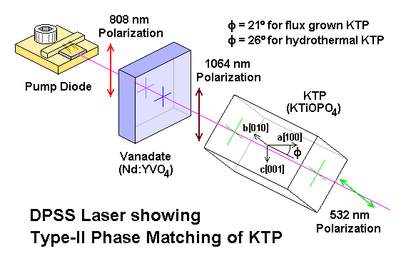
The green lasers we are all used to here do not have a "green diode"

They use a powerful Infrared diode to pump a solid state crystal that doubles the frequency to produce green.

Sam's Laser FAQ: Welcome Page

Green-laser-pointer-dpss-diagrams.jpg


ktppm.gif


One of my green lasers easily cutting a plastic cup.

cup1.jpg


two greens from 50 feet away, no smoke or fog.

twins.jpg


destroying a chunk of dry ice....

c02a.jpg


lasing.jpg


0222.jpg
How powerful was it?
 
Do you use yahoo messanger or aim? this might be easer to be walked through, I opened the ground on my diode and put my dmm in series measuring amps and the circuit is pulling .012 amps

Sorry, i have nothing other than skype here ..... anyway, 0,012A is decisely too low ..... for an 1W IR, it must be one ampere or more, depend from the diode type ..... sure that your driver is working correctly ? ..... have you tried it with a high power test load ? (like, 4 diodes BY255 type, plus an 1 ohm 5W, all in serie)
 
I built another driver and the still nothing but this one the regulator actually get hot and iam getting .789 amps out of, http://3.bp.blogspot.com/_4wHo2MPDwAc/R2YuBFTq09I/AAAAAAAAAAU/4FCiHm71rQE/s1600-h/Driver.jpg that is the electrical schematic I followed but I only used 1 4 ohm resistor. what I dont under stant tho is why on thee is the negative side of the diode and the negative side of the capasitor on the positive side of the circuit? and why do they tie the 2 legs of the potentiometer together I thought it they would ure it to adjust the voltage? Sorry about all the questions but this is my first laser anbd I really want to understand it, I have been reading averything I can find on them and also how to check all the components and that why I was wondering about the negative side of the diode and capasito in the positive side. How would you build the circuit would it be like thae one I built? My skype is terrance.rowe
 
Last edited:
That schematic is wrong.

and also, the diode shown have the negative on the case (central pin), so is a red diode, not an IR diode (they have the case as positive ..... if they are 2 pins case, there's no problems, if they are 3 pins case, the central is connected to the case and is the positive ..... wait, i'm taking some pics, so is more clear)
 
the negative part of the silicon diode has a grey ring around it and the longest leg on the capacitor is the positive just like normal led's.

stuart :)
 
Ok, now ...... first of all, the diode ..... as you can see, there's 2 different styles for the 9mm cans, 2 and 3 pins ..... for the IR diodes, and ONLY for the IR ones, these are the polarities:

attachment.php


Second, that schematic was wrong ..... i personally always use this one, that also grant a bit more survival to the trimmer ..... changing the values of the 2 resistors, it can be made for different ranges of current, and is also much more stable (and just for safety, you can add also a 470 or 560 ohm resistor in parallel to the output, so it discharge the capacitor when there's no diodes connected and avoid that you can fry the LD connecting it to the driver with a charged capacitor)

attachment.php


BTW, you can also use the LM1117 with the same schematic, for have a less dropout ..... but, for an 1W diode, it may be not enough to use a single regulator, or at least it require a lot of heatsinking ..... in this case, the LM117 (is different from the LM1117) is better, cause it work with higher temperature limit .....
 

Attachments

  • LM317driver01.jpg
    LM317driver01.jpg
    87.1 KB · Views: 17,867
  • 9mmircases.jpg
    9mmircases.jpg
    301.6 KB · Views: 6,705
Hmm looks like iam going to have to get more parts, so did I blow up my diode then? I mean in the diode function on the dmm it still reads like a normal diode. Ya I thought that schematic might have been messed up my diode only had 2 legs.
 
Is possible that your diode is broken, but being an 808nm, it's hard to say yes or no with bare eyes .....

You need a webcam that show the IR (the cheapest ones usually don't have anti-IR filters in the lens assembly), or a photocam or videocamera that can see IR ..... for try if they see the IR, just point them on the led of a TV remote control and press a key, if you see light flashes, they see IR .....

Now, set your diode in some stable holder (also a third hand / helping hand is ok for a quick test), and connect it to your driver in the correct way, with the trimmer in the maximum resistance position, and point the diode to a wall or a flat surface, non reflective (cardboard, paper or similar) at 10 or 15cm of distance, point the webcam/camera on the same point on the wall/cardboard/whatever you use, and power up the diode (NEVER point the camera directly to the diode ..... no reasons for risk to damage it)

At this point, if your diode still emits something, with enough current you must see some light on the wall, through the camers (not at eyes) ..... the schematic that i have posted, with these values, permit you to change the current from approximatively 80mA to approximatively 430mA (enough for test the diode and see if it lase), and usually those diodes have a threshold (current where they start to lase) around 160/180mA ..... at low current, you probably see just a very faint halo of light, with no defined shape, like this

attachment.php


Slowly increasing the current, if the light remain the same, or increase a bit, but not take a defined shape, then your diode is LEDed (it don't lase anymore, and you can throw it away) ..... as example, also this one is LEDed ..... very bright at 650mA, but no lasing, just a spot

attachment.php


If at a certain point instead the light halo change shape, assuming a shape like these ones, and remaining "in shape" increasing the current, then it still lase (don't keep these tests more long that 5 or 10 seconds, in these conditions and without a heatsink) ..... just after the threshold level:

attachment.php


and at 300mA:

attachment.php


also this one is lasing ..... more large shaped bar, but still stable and coherent

attachment.php


If instead you see "half bars", or bars with black spots or lines through them, or very deformed, the diode is still lasing, but the chip is damaged, and you can throw it away.
 

Attachments

  • ird01.jpg
    ird01.jpg
    60.8 KB · Views: 3,410
  • ird02.jpg
    ird02.jpg
    75.4 KB · Views: 3,368
  • ird03.jpg
    ird03.jpg
    83.7 KB · Views: 3,353
  • ird04.jpg
    ird04.jpg
    88.3 KB · Views: 3,392
  • ird05.jpg
    ird05.jpg
    93.8 KB · Views: 3,369
  • ird06.jpg
    ird06.jpg
    90 KB · Views: 319
Ok I got the stuff kinda but the electrolytic capacitors are 35v instead of 16v will that work? also I could not get ahold of a 3.3 ohm resistior to save my life. but i got everything else i guess. what else could i use to replace that 3.3 ohm resistor?


Back
Top